OpenSprinkler › Forums › Hardware Questions › OpenSprinkler Pi (OSPi) › OpenSprinkler PI stopped working…
- This topic has 11 replies, 3 voices, and was last updated 6 years, 2 months ago by
AKADAP.
-
AuthorPosts
-
May 1, 2020 at 12:18 pm #65569
AKADAPParticipantI noticed today that a sprinkler that should be on was not. I checked the OpenSprinklerPi control web site, and it thought it was wattering.
I tried stopping and re-starting the sprinkler, but it did not turn on.
I rebooted the Raspberry pi, but the sprinkler still could not be turned on.
I measured the voltage on the sprinkler, and it was zero.
I measured the voltage from the transformer, and it was correct.
I’m using a raspberry pi 4, so I unplugged the USB-C to verify that it was still being powered by the sprinkler transformer, it was, so the transformer was properly connected to the OpenSprinklerPI.
I tried turning on the other sprinklers, none would turn on.
This system was working previously, but has spontaneously stopped working.
I will shut down the system and disassemble it later today to see if I can see anything wrong.
Is there any error checking going on with the I2C connection that would report an error if the I2C was not working?
Any other suggestions for things I should check?May 1, 2020 at 12:19 pm #65599
RayKeymasterFrom the symptom it’s not obvious to me what’s the cause. This has nothing to do with I2C because OSPi does not use I2C for controller valves. It uses a shift register (74HC595). Some basic things you can check is the VIN-GND voltage (these pins are available at the top-right corner of the PCB). It should be about 5V when it’s powered.
May 2, 2020 at 10:44 am #65604
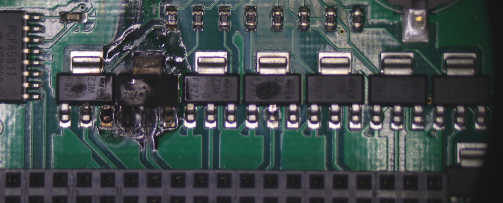
AKADAPParticipantOnce I disassembled the setup it was obvious what had failed.
Three of the triacs are obviously fried. One so badly that its pads have come loose from the circuit board.
All of the 220 ohm gate resistors are damaged. They show discoloration in the center, and none measure 220 ohms. The lowest resistance I got was 300 ohms, some were in the 100s of k.I am running a Raspberry pi 4. This Raspberry pi can draw more than the 1 amp that the OpenSprinkler pi can provide, especially if one wants to connect anything to its USB ports which I had not done, but was thinking about adding to the system.
I followed the recommendation to power the PI through the USB type C port.The following is my best theory of what happened:
In measuring the solenoids through the 50′ of wire, two of them measured 20 ohms. This is lower than it should be.
There appears to be no current limiting other than the transformer itself on the AC input.
There appears to be some accidental protection against shorted solenoids since usually the raspberry pi is powered by the AC, and if there is a short, the AC voltage will drop to near zero, killing the power to the Raspberry pi, resetting everything, and shutting off the Triacs.
By adding the additional power supply on the USB C port, this shutdown did not happen, the Triacs stayed on, drawing more current than they were designed for, overheated, and eventually burned out. I’m not entirely sure why the gate resistors also burned, but this happened on every single gate transistor, including two that never had a solenoid connected to the associated triac.
For safety, I think there should be a fuse between the AC connector, and the Common connector.If OpenSprinkler decides to spin the board to add a fuse, I would suggest that they also spread out the traces between the two 40 pin headers. Packing those traces so close together on a two layer board is begging for crosstalk. You get away with this now since you are not using those signals, but anyone trying to use that second connector is going to have problems. The alternative is a four layer board with two ground layers, but that is more expensive.
The package you are using for the triacs is designed to transfer heat to the circuit board. Unfortunately, this design does not have any place for that heat to go. Ideally you would have about a square inch of copper connected to the large pad to act as a heat sink.
I’d also like to see some way for the Raspberry pi to detect when a solenoid is malfunctioning. These solenoids are out in the elements and will eventually fail. I’d rather not have to replace my sprinkler controller every time a solenoid fails, or run for months thinking I’m watering when I am not.
Attachments:
May 2, 2020 at 10:44 am #65611
AKADAPParticipantI was looking at the specifications for the OpenSprinkler pi (reproduced here):
Specifications:
Input Voltage:22V AC to 30V AC.
DC Output Current:500mA @ 5V (to power RPi).
Number of Zones:8 on the OSPi, expandable by linking zone expansion boards.
AC Output Current:800mA continues @ 24V AC per zone / station, 8A impulse / inrush.
Over-voltage Protection:48V bi-directional TVS on each zone, AC input, and rain sensor terminal.
Over-current Protection:2A on AC input; 1A on 5V DC.
Size:135mm x 100mm x 32mm (5.3” x 4” x 1.26”)
Weight:150g (5.3oz) w/o RPiI don’t see where the over-current protection comes from.
For the AC, I see one connector directly connected to GND, the other connected directly to the COM connector. The triac connects the pin of the solenoid directly to GND. I see no circuitry to limit the current.
For the 5V, I see a switching power supply configured for 2A with a 12V input This part has a current limit, but it is significantly higher than 3A. I don’t see any other current limiters on the 5V.
I do see the TVS diodes for voltage limiting, I just don’t see any circuitry for current limiting.
Can you tell me how you came up with the over current protection numbers?May 2, 2020 at 10:55 am #65623
RayKeymasterAre you sure this is caused by solenoid shorting? 20ohm resistance is within acceptable range. The damage could be caused by power surges, or voltage spikes induced by lighting etc.
About fuse: it’s difficult to decide the fuse rating — many users want to open multiple solenoids at the same time, which will trip the fuse undesirably. So we can’t decide whether the fuse rating should be 500mA, 1A, 2A or what. We’ve had batches of OSPi in the past that have on-board fuse, but there are false triggerings so in later batches we decided to leave this as a choice for the user — if you want to add a fuse, you can decide what’s the current rating you want.
The triacs we use (Z0103MN) has on-state maximum current of 800mA to 1A, which is in its datasheet:
https://media.digikey.com/pdf/Data%20Sheets/ON%20Semiconductor%20PDFs/Z0103_107_109MN.pdf
All transistors have specified maximum on-state current. This has nothing to do with over-current protection. The maximum on-state current refers to the maximum amount of current that each transistor is able to handle, beyond that it might burn out. Nowhere in the user manual did we say there is over-current protection of 800mA on each channel. The total over-current protection of 2A was from the previous batch when there was on-board 2A fuse, so I admit that’s no longer there and should be removed. Over-voltage protection is done by TVS diode for each zone, that’s for voltage protection, not for current protection.Non-fuse based current limiting circuit for each zone is not trivial to implement and will significantly increase the cost of the circuit. If you have any idea how to implement non-fuse based current limiting circuit for each zone, and this is for AC current, let me know, I would be curious to know.
May 4, 2020 at 7:44 am #65626
AKADAPParticipant20 ohms through 50′ of cable is not within the acceptable range, 20 ohms at the solenoid is at the very low end of the acceptable range.
Lightning is something we get about once every other year here, and then usually at least 5 miles away, so no it is not lightning. At this location I seldom have power fluctuations. It is only the triacs and gate resistors that have fried. The only way for current to go through them is through the solenoid. The only way for enough current to go through the solenoid to fry it is if the solenoid is bad. I have six identical solenoids, and the resistance is significantly different between them.
It is the only plausible explanation that I have been able to come up with.I have ordered a replacement Open Sprinkler Pi. I will put a fuse in series with the AC. I have also ordered replacement solenoids. We will see if the new unit survives more than a month.
I mostly do digital electronics, and some low voltage analog, so I am not too familiar with power electronics, but I’ll take a look, and see what solutions are available.
May 4, 2020 at 7:44 am #65628
AKADAPParticipantMy first suggestion would be to replace the triac with a solid state relay. The triac is a bipolar device, and has a significant voltage drop. This means that power is dissipated in the device causing it to heat up. Solid state relays have very low on resistance so they dissipate very little power. You can also get them with high enough current ratings that the transformer for the AC could not provide enough current to fry them. Also in most cases, the input is an LED, so with a current limiting resistor for the LED, there is no chance of frying the drive circuit. An example of a part like this is this: https://www.digikey.com/product-detail/en/toshiba-semiconductor-and-storage/TLP241AF-TP4-F/TLP241AF-TP4FTR-ND/7652708
Yes, this would increase your BOM cost by about $10, but that is better than burned boards.
These parts are also completely isolated, so one side of the AC would not need to be hard wired to GND, and you could use a full wave rectifier instead of the half wave rectifier you are currently using for the 5V power supply. It would be nice to have a big enough power supply to power a Raspberry Pi 4 with a few peripherals.Resettable fuses are so cheap you could use one one every channel: https://www.digikey.com/products/en/circuit-protection/ptc-resettable-fuses/150?FV=69%7C409393%2C686%7C150723%2C686%7C150724%2C686%7C153583%2C686%7C157293%2C686%7C160817%2C686%7C213650%2C686%7C257642%2C686%7C257644%2C686%7C257645%2C686%7C287637%2C686%7C287639%2C-8%7C150%2Cmu1.1A%7C683%2Cmu1.2A%7C683%2Cmu1.5A%7C683%2Cmu1A%7C683%2Cmu2.2A%7C683&quantity=0&ColumnSort=1000011&page=1&stock=1&rohs=1&nstock=1&k=fuse&pageSize=25&pkeyword=fuse
May 4, 2020 at 7:44 am #65640
pcichockiParticipantMy unit (old 2.1 version) recently also stopped working. It does not start. Ray (thanks) tried to help me but without effect. So i had to do something quickly to water my garden (11 zones). Buying new unit takes a time. So I took raspberry, old SATA cable and connected this two things. According to source code you can use this pins to connect relay.
#define PIN_FREE_LIST {5,6,7,8,9,10,11,12,13,16,18,19,20,21,23,24,25,26} //
No soldering, only parts i used are relays, power supply, non modified opensprinkler software installed according to user manual.
Works quite well except rain sensor (it should be connected using PCF8591 – it is more time consuming to connect it.
I also tried to connect zone expander with shift register (2.1 version) then i will not need relays. Unfortunately i only found connection schema in OSpi manual from side of raspberry. I tried to analyse eagle PCB schema of zone expander but no success and i do not want to fry my expander. So for emergency you can try version with relays. Take a look at picture.
Regards
PiotrMay 4, 2020 at 8:27 am #65673
RayKeymaster@AKADAP: from my experience, 20ohm for solenoid resistance should be ok — please note that solenoid is a big inductor that has reactance to AC current, so even though the resistance seems low, it actually has a much larger impedance to AC current. In any case, if you found that the resistance is significantly different from your other solenoids, then I think it’s fair to say that indicates a problem.
- Thanks for pointing out solid state relays — I was fully aware of it but made a conscious decision not to use them, for several reasons. One, several years ago when I first started working on the project SSRs are quite expensive, like 3 to 5 bucks each piece — while it’s feasible to use them in a DIY project, using them in massive production will significantly increase the cost. It’s not just BOM cost — manufacturers always add some percentage of margin, also customs duty tax is based on declared value, so that can end up increase the cost by several folds. I agree that now they are much cheaper than several years ago, still there are challenges with choosing them — a lot of SSRs with sufficiently high on-state current (i.e. more than 500mA) have relatively low breakdown voltage (<=40V), which put them at the very edge of acceptable range (24VAC adapter often has no load voltage measuring up to 30VAC, so the peak voltage can exceed 40V).
- Besides, I’ve taken apart many commercial controllers, and all of them universally use triacs — I have never seen any that uses SSRs. Some use opto-couplers to drive triacs, which provide isolation; some use much bigger triacs which can withstand more power dissipation. But frankly none of them alone prevents triacs from burning out due to solenoid shorting, or damage due to lightening. Opto-couplers or SSRs do provide isolation, but that doesn’t mean the triac or SSR itself cannot be damaged. If some zones stop working, either we have to repair the circuit, or toss it out and provide a replacement. At least with triacs they are cheap to replace. If I had to take a guess, I would think the bigger companies that make sprinkler controllers probably realized there is a cost-benefit tradeoff — triacs are crude but they are at a fraction of the cost of SSRs. If adopting SSRs increase the reliability by 10% but adds cost by 50%, it might not be worth it.
- When circuits are produced in large quantity, there are always things that can go wrong in ways that you may never have thought of. For example, I’ve seen relays that don’t click or don’t make contact when clicking. I’ve seen controllers that work perfectly fine when we tested but just won’t work at the customer’s end. While SSRs seem like the perfect solution, I fear that there are other issues entailed by it that I may have not even thought of.
- So, I agree that adding fuse is a very cost-effective solution. Resettable fuse unfortunately does not really work in this setting: they trigger slowly and do not respond well to instantaneous current spikes. Also, as I explained above, users who want to turn on multiple solenoids at the same time do not want to undesirably trip the fuse. Another solution I have seen on some other sprinkler controllers is a big-ass power resistor,like cement resistor, in series with the COM line, to limit current upon solenoid shorting. This is something interesting to try, though picking the exact resistance value is just as difficult as picking the right fuse rating. So in the end, I think it may be best to leave this as an external component that’s easy to replace, as opposed to making it a built-in component on the circuit board.
- Anyways, all that I am trying to say is that I’ve put thoughts into various ways to improve the circuit design, and in the end made the conscious decision to stay with its current form. The decision is not made solely based on reliability, but there are economic considerations. If you are worried about reliability, I do recommend adding an external fuse, or use an external relay board like pcichocki described or shown in this post. I hope this makes sense.
sorry about using bullet list — for some unknown reason bbpress is removing all my line breaks, so had to use bullet list to force line breaks.
May 4, 2020 at 11:48 am #65712
RayKeymasterI was gonna add one more thing but managed to forget: you may be aware that we also sell DC-powered OpenSprinkler (microcontroller-based one, not OSPi unfortunately). This is my own creation, while all other sprinkler controllers on the market use 24VAC and triacs. The thinking behind developing DC-powered controller is that I consider 24VAC an old technique that should be obsolete. 24VAC transformers are bulky, expensive, and not universal (i.e. same transformer does not work in all countries). On the other hand, DC power adapters are much smaller and cheaper. The DC-powered OpenSprinkler uses MOSFETs, which are much more efficient switches than triacs because, as you mentioned, the voltage drop across a MOSFET switch is very very small so they can run a lot more current.
I have always hoped that the industry will move more towards DC-based system, but it seems no one has any incentive to replace them. Some companies like US Solids, have created motorized ball valves that work with a wide range of voltage (like their 9-24V AC/DC series). I am really hoping to see more of these changes and innovations, because I believe 24VAC should be made obsolete and replaced by more modern systems.
May 11, 2020 at 10:14 am #65891
AKADAPParticipantI got a replacement open sprinkler pi, and replacement solenoids. I also bought some self resetting fuses rated for 500 mA (supposed to trigger at 1A, and handle 60V. I modified the open sprinkler pi to have a fuse in series with each valve connection.
I replaced the solenoids, and measured the resistance at the end of the cable, I got reasonable numbers.
I measured the solenoids I removed from the sprinkler valves, and they all measured 25.4 ohms.
Anyway, at this point I reconnected the sprinkler controller and tried to test it. The sprinklers would turn on then less than a second later turn off.I removed the resetable fuses an tried again, this time with a current probe on the output of the power supply. I was seeing 0.9A when a sprinkler was running with occasional spikes to 2A. I was running each sprinkler in sequence, one minute each, when it got to the sixth and last sprinkler, I saw a spike of more than 4A (I was on the 4A range on the meter), and a triac and its associated gate resistor smoked.
I replaced the triac with a new one, and I checked the cabling. There were no cuts in the cable, on only the very end near the sprinkler valves has ever
gotten wet. I did notice that there was a bunch of extra cable coiled up near the sprinkler valves in the crawl space under my house.I tried connecting up the sprinkler controller again. This time I only used the AC to power it, I did not connect the USB C power.
When I tried to test it, it turned on the 1st sprinkler, the current spiked, the pi reset, and the sprinkler turned off.I removed the sprinkler controller, and connected the transformer directly to one of the sprinkler valves. The current was hovering around 0.5A with occasional spikes to 2A.
I tested each of the solenoids I had previously removed from the valves (not the new ones) and found that they only drew between 300 and 330 mA.
At this point I suspect that the power supply is behaving badly with the long cable. The power supply I was using has an LED, which makes me believe that it internally has something more than just a transformer. If there is some form of protection circuit that is partly triggering such that it only shuts off the output on the positive, or only the negative half of the waveform, it could be driving a large DC component into the solenoid. The DC signal would not see the inductance of the solenoid, and therefore could drive much more current. This is a rather sketchy theory, but it is the best I can come up with.I removed the extra cable from the sprinkler valve end of the cable, this measured 42′, so originally I had 100′ of cable, and now I was down to 58′.
I have another power supply that I am pretty sure is just a transformer. It is only rated for 0.8A.
I tested the solenoids installed in the sprinkler valves by directly connecting them to the transformer. I found that they draw between 250 and 300mA.I re-install the resettable fuses. These fuses have about 1 ohm of resistance. I re-connect the controller and test. I find that while the solenoids buzz, the sprinklers either don’t turn on, or barely turn on.
Tomorrow, I will bypass the fuses and try again.
May 11, 2020 at 10:14 am #65898
AKADAPParticipantI bypassed the fuses, and the open sprinkler pi appears to be working now. It is drawing about 300 mA when a valve is open.
Summary:
I believe the primary cause of the problem was a bad power supply.
I replaced the solenoids, but I don’t think this made any difference.
I shortened the 100′ cable by 48′. I think this extra length might have helped trigger the bad behavior of the original power supply.
I replaced the AC power supply.
I removed the power supply from the USB C connector. I believe that having this power supply defeated an accidental safety behavior. If something shorted one of the solenoids, it will kill the AC voltage. If the USB C power is not there, this will cause the PI to reset, and shut off the shorted solenoid. If the USB C power is is place the Pi remains powered, and the solenoid will remain on with the likely result of the triac burning up. -
AuthorPosts

- You must be logged in to reply to this topic.
OpenSprinkler › Forums › Hardware Questions › OpenSprinkler Pi (OSPi) › OpenSprinkler PI stopped working…