OpenSprinkler › Forums › Hardware Questions › OpenSprinkler Pi (OSPi) › Smaller DC version of OSPi
Tagged: OSPi mini DC
- This topic has 10 replies, 2 voices, and was last updated 8 years, 11 months ago by
Ray.
-
AuthorPosts
-
May 20, 2017 at 1:10 am #46308
Uksa007ParticipantHi,
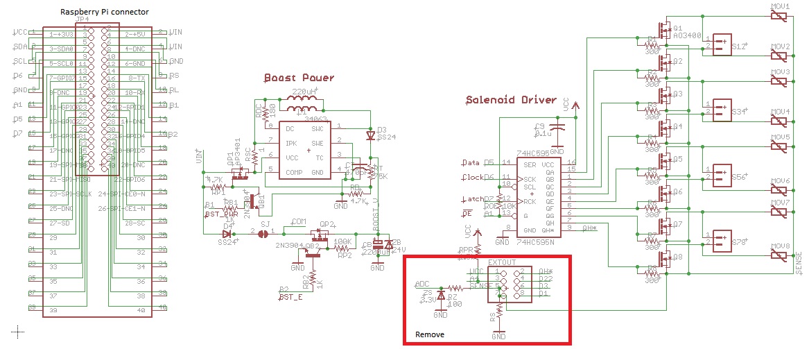
I’m in the middle of putting together a schematic and board layout for a smaller DC version of the OSPi similar to the OSBee V2, initially it will be 3 or 4 Channel shield kind of design.
edit (Managed to squeeze in 8 channels!)I’m trying to design it so that it will run off the 5v supplied from the Raspberry Pi (my plugpack is 2.5A)
I note that the output stage for:
OSBeeV2 uses a 4 FET design
Open sprinkler DC uses a single FET design.Is there a advantage in using either the 4 FET or single FET design?
Will the current firmware for the OSPi support the DC design?
If so is there a preference for which PINs on the Raspberry Pi I should connect BST_PWR and BST_E?Regards.
May 20, 2017 at 5:10 am #46311
Uksa007ParticipantI have made some progress and made some executive decisions, which can easily be changed:
1) Opted to use the Single FET design, makes more sense to me.
1) BST_PWR (which powers up the boost circuit) has been connected to GPIO1
2) BST_E (which turns on the +24V to the COM terminals) has been connected to GPIO4Other things I have tried to keep as standard from the original OSPi eg:
Data D5 = 13-GPIO2
Clock D6 = 7-GPIO7
Latch D7 = 15-GPIO3
!OE A1 = 11-GPIO0ADC:
So I was trying to avoiding having to include an ADC.
How important is it that the SENSE voltage is available to the software?
Is it used for information purposes or protection to ensure you are not driving too much current?
Can I omit it?Attachments:
May 20, 2017 at 7:14 am #46313
Uksa007ParticipantSo got the unified firmware running on the Pi, have not found any options to configure the hardware.
Its reporting:
Hardware OSPi – ACI probably need to create a new hardware type or modify one of the existing hardware types.
Think I’m going to need a OSPi mini – DC, eg OSPi with DC support.
Is there any way to configure the hardware types using configuration files, or do I need to crack open the source?anyone?
May 20, 2017 at 9:45 am #46314
Uksa007ParticipantAnswering my own questions, I found the pin assignments in define.h and modified the Opensprinker.cpp to define the hardware as DC with no current sensing.
Rebuilt Opensprinkler and now my About page reports:Hardware: OSPi – DC
YAY I will take that as a WIN!!!!!
It’s a bit of a hack, but for testing it’s a start!
May 21, 2017 at 4:08 pm #46370
RayKeymasterTo answer you original questions:
– Is there a advantage in using either the 4 FET or single FET design?
OSBee operates latching valves and for that reason, it needs each zone to use a half H-bridge to be able to reverse the polarity of voltage. This is different from OS DC, which only operates non-latching valves, and hence a single FET is sufficient.– Will the current firmware for the OSPi support the DC design?
It should be able to. The difference in AC vs. DC is mainly in the circuit design and not so much in firmware. In fact, the primary difference in the firmware code is quite small — because OS DC needs to boost the voltage to energize the valve, the apply_all_station_bits function has additional code to turn on the boost converter in order to boost the voltage. If you don’t need the boosting stage (say, because your valves are all 12VDC and your input voltage is already 12VDC), then you don’t even need the boosting stage. In that sense the AC and DC has really no difference in firmware code.– If so is there a preference for which PINs on the Raspberry Pi I should connect BST_PWR and BST_E?
BST_PWR basically controls the input voltage into the boost converter. When it’s enabled, the boost converter starts and bumps the input voltage to about 22VDC into the 2200uF capacitor. BST_E controls the output path — it should be disabled when BST_PWR is turned on, because having the output path enabled may affect the boost converter and make it no able to successfully boost the voltage. Once the capacitor is charged, turn BST_PWR off, and BST_E on, that way, the boosted voltage will be present on the output path. In the firmware code (apply_all_stations_bits function) this is pretty clearly shown there. You can use any available pins for BST_PWR and BST_E — these are just general purpose output pins, nothing special.June 12, 2017 at 6:30 am #46675
Uksa007ParticipantThanks Ray,
I have been hard at work and have created PCB layout about to send it off to be fabricated.
Couple of questions re substitute parts:
1) The 220uH inductor for the boost circuit, are there any specs for current and resistance?
One available locally is RLB0912-221KL 220uH, RMS current 440 mA, 0.74 ohms is this one suitable?
http://www.farnell.com/datasheets/1647944.pdf?_ga=2.80422039.1263943725.1497055596-1758119718.14926628982)QP1, QP2 AP3401 or BSS84
The P-Channel FETs to turn on the boost and fire it.
AP3401 doesn’t seem to exists(miss-type?), should this be AO3401?
I assume that the BSS84 can’t handle enough current?
AO3401 isn’t available locally will a DMG2307L be ok, datasheet below?
http://www.farnell.com/datasheets/1915926.pdf?_ga=2.41980133.111771980.1497254896-1758119718.14926628983) N-Channel FETs to switch the Solenoids to GND, Q1-8 AO3400 or BSS123
AO3400 not available locally, assume BSS123 can’t handle enough current?
ZXMN3F30FHTA is available locally will it be ok, data sheet below?
http://www.farnell.com/datasheets/2097584.pdf?_ga=2.41015650.111771980.1497254896-1758119718.14926628984)Should I optimize the Boot circuit to operate more efficiently on 5V input voltage?
I notice you different values in the OSBee for the capacitor and resistor around the 34063 boost converter.
Is the Osbee optimized for 5V input?Thanks for your time!
June 13, 2017 at 9:38 am #46747
RayKeymaster1) 220uH inductor: your RLB0912-221KL should be fine. I don’t really have any specific numbers for the current and resistance values, but I think it should be rated 330mA at minimum (because the 1 ohm current limiting resistor that goes with MC34063 limits the current to 330mA). Since the booster is only turned on for a very short period of time, the inductor current isn’t as critical as in situations where the booster needs to remain on constantly.
2) Yes QP1 and QP2 are AO3401, not AP3401 (and should not be BSS84 because BSS84 cannot handle high current). Your DMG2307L seems a suitable substitute.
3) Same, the N-MOSFETs should all be AO3400, not BSS123. Your ZXMN3F30FHTA seems ok. The only concern is if you look at the Drain Current output characteristics, under 3.3V Vgs, the current seems to saturate at about 1 amp. This performance is worse than AO3400. Still, if your application doesn’t require more than 1 amp of current, it should be ok.
I am a bit surprised that AO3400 and AO3401 are not available where you are — these are quite common parts.
4) I don’t think the Booster circuit needs to be optimized — it should work pretty well under a wide range, at least 5VDC to 12VDC. You said “I notice you different values in the OSBee for the capacitor and resistor around the 34063 boost converter.” can you be more specific about the different values? A few quick notes:
– If you mean the current limiting resistor, I’ve frequently used 1 ohm. It can be higher or lower, the tradeoff is that higher resistance leads to lower current, so it takes longer time to boost but the plus side is that you can use smaller inductor since it doesn’t need to run high current; conversely, lower resistance leads to higher current, so it’s faster to boost, but the inductor needs to withstand higher current.
– By capacitor I suppose you mean the timing capacitor. It (together with the 180 ohm resistor) controls the switching frequency and this can really vary a lot. For example, the capacitor can be anywhere between 150pf to 470pf; resistor can be anywhere between 100 ohm to 470 ohm. There isn’t any one set of correct values.June 14, 2017 at 9:54 am #46789
Uksa007ParticipantHi Ray,
Thanks for taking the time to look at the substitute parts.
3) Q1-8 the N-MOSFETs should all be AO3400,
For some reason I had it in my mind that the 74HC595 latch was using 5V Vcc, but you are correct it using 3V3, so the N-Mosfet will be limited to 1A which might be a bit low, not really sure of the inrush current required to turn on the average solenoid.I too was surprised that the AO3400 is not available from Element14
This seems to be Element14 substitute so I might go with it
http://www.farnell.com/datasheets/1911844.pdf?_ga=2.122560779.1206234277.1497427852-1758119718.14926628984) Booster circuit optimized for 5V input.
I have been scratching my head trying to work out how you came up with the component values.
OSDC uses RT 27K and RB 1.6K, CT 330pF
OSBEE Uses RT 75K and RB 4.7K, CT 470pFUsing this calculator I get close to your values for OSDC, using a 9V input (OSDC transformer)
I guess I will go with these and can adjust if need be.
http://www.gmsystems.com/switching-reg-calculator-for-mc-34063-or-mc33063.htmlUsing these values for input
Vin 9V
Vout 22V
Iout 55 mA
Vripple 1.8 mV(pp)
Fmin 77kHzIt calculates the below, of note are the R1 and R2 which are the voltage divider for the comparator are way off from your values for OSBee R1 and R2?
Ct=325 pF
Ipk=294 mA
Rsc=1.02 Ohm
Lmin=221 uH
Co=2236 uF
R=180 Ohm
R1=1.2k R2=20k (22.08V)Thanks again.
June 18, 2017 at 12:52 am #46828
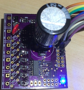
Uksa007ParticipantMy PCB’s and parts are on order.
While I’m waiting on hardware I would like to improve the firmware “hacks” I made.
I have forked the Opensprinkler-Firmware. https://github.com/Uksa007/OpenSprinkler-Firmware
Thinking I should probably create a new hardware type for my OSPi-DC, as it is fairly different, no RTC, Buttons, or ADC and as a result the pin defines are a little different.defines.h seems to define the hardware and pins, whats the best way to go about creating a different hardware version of the OSPI?
/** Hardware version base numbers */
#define OSPI_HW_VERSION_BASE 0x40/** OSPi pin defines */
#if defined(OSPI)Have gone with creating a new hardware type OSPIMINI and have updated many files to include new hardware type.
July 11, 2017 at 8:48 pm #47090
Uksa007ParticipantSo I have received my boards and assembled one.
Preliminary testing at the moment and it’s working great.
The Boost circuit produces about 22.5v.My software modifications are working great, see fork link above.
Tested with some solenoids and they open and stay open OK with no water pressure.
However when there is water pressure they open OK, but then close almost immediately (after the booster is turned off).
Seems the 5V is not sufficient to keep them open.
I’m using the below 12V DC solenoids
http://www.ebay.com.au/itm/3-4-DC12V-PP-N-C-Solenoid-Electric-Valve-Water-Control-Diverter-Device-New/381978081748Ray does the OpenSprinker DC drive the solenoids OK when run from 5V eg USB?
Solved my issues:
There was too much resistance in the cable from the OSPi Mini to Solenoids (10m run), resulting inadequate current to hold it open.
Fix: Doubled the conductors and she working like it should!Attachments:
July 24, 2017 at 10:10 am #47250
RayKeymasterGenerally to find out how a macro define is used, you can do a global search of the macro name (e.g. OSPI_HW_VERSION_BASE) and that will give you an idea of where the macro define is used. Then you can clone it into a different macro and just duplicate the sections where it appears.
From the updated message and it seems you were able to figure things out. The wire definitely needs to be sufficiently thick otherwise the resistance on the wire will drop too much voltage.
-
AuthorPosts
- You must be logged in to reply to this topic.
OpenSprinkler › Forums › Hardware Questions › OpenSprinkler Pi (OSPi) › Smaller DC version of OSPi