In the past I’ve written several blog posts about how to use Arduino to interface with remote power sockets. For home automation involving powerline devices (e.g. lights, heaters, pumps, fans), this is my favorite solution, because it’s low-cost (remote power sockets are widely available at cheap price) and convenient (no messing around with relays and powerline wires). Also, one Arduino plus transmitter can simultaneously talk to many power sockets, making this a scalable solution too.
With the just released OpenSprinkler firmware 2.1.1, support for interfacing with remote power sockets has finally arrived. So you can now use OpenSprinkler not only to control sprinkler valves, but also powerline devices. Trying to find a programmable way to control your Christmas lights? Look no further! With OpenSprinkler’s easy-to-use web interface and flexible programming capability, you can enable automated control of lights, heaters, pumps, fans — anything that can be plugged into wall outlets.
Here is a quick video tour on how to get started:
Below are detailed instructions.
Required Parts:
- OpenSprinkler 2.0, 2.1, 2.2 or above.
- 433MHz Radio Frequency (RF) transmitter-receiver pair.
- RFToy.
- One or more remote power sockets, preferably those with separate on/off buttons.
How does this work?
Let me briefly explain how the whole thing works. First, common remote power sockets operate in the 433MHz radio frequency band. When you press a button on the remote, it sends out a signal to the power socket, which gets decoded and acted upon. If we can sniff the signal, we can use a microcontroller plus a 433MHz transmitter to replicate the signal, thus be able to directly control the power socket in software. The RFToy is a gadget that I’ve designed to easily decode signals from common remote power sockets. Once we have the code, we can use OpenSprinkler to simulate the code, thus be able to control remote devices.
Heads-up: the following steps require a small amount of soldering. The estimate time for modification is 15 to 20 minutes.
Step 1: Decode Remote Power Sockets
Take out the RFToy, plug in a 433MHz receiver (making sure the VCC and GND pins on the receiver match the +5V and GND pins on the RFToy). Follow the on-screen instructions to record the on/off signal of a power socket. Once decoded, the signal will be converted to a 16-character hexademical code.
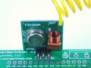
To test if the code works, take out the 433MHz transmitter, and solder a 17cm (6.7inch) long wire antenna to the ANT pin. Then plug it into the RFToy (making sure the DATA and GND pins on the transmitter match the DATA and GND pins on the RFToy). Bend the pins as necessary. Now click button S3 or S1 on the RFToy, the power socket should be toggle on or off just like when you press the buttons on the remote. Keep in mind that although most remote power sockets work in the 433MHz band, there are some that work in the 315MHz band. In that case, just use a 315MHz transmitter-receiver pair.
Step 2: Install RF Transmitter to OpenSprinkler
Remove the OpenSprinkler enclosure, and locate the RF transmitter pinouts (marked A3 VIN GND). The pinouts are located either close to the top of the PCB, or next to the Ethernet jack. Plug in the transmitter to the pinouts, making sure the DATA-VCC-GND pins on the transmitter match the A3-VIN-GND pins on the circuit board. Then solder the three pins at the back of the circuit board, and clip as necessary. Carefully arrange the wire antenna around the LCD and re-install the enclosure.
It’s important to use a wire antenna of sufficient length, otherwise the transmission range will be severely limited.
Step 3: Final Testing
Make sure your OpenSprinkler is running firmware 2.1.1 or above. If not, please follow the firmware instructions to upgrade your firmware first. Then go to Edit Stations, select the station you’d like to use as an RF station, and change its name to the 16-character hexademical code recorded on the RFToy. Any station with a name of this form will be automatically recognized as an RF station. When the station is turned on, the controller will automatically send out the signal through the installed RF transmitter, thus turning on the corresponding power socket (and vice versa for turning off the station).
Three quick notes:
- The normal station function still works (i.e. if there is a sprinkler valve connected to that station, it will be switched on/off accordingly).
- Most likely you want to turn off the ‘sequential’ flag for RF stations. This is because unlike sprinkler stations, you probably don’t want RF stations to be serialized with other stations.
- If you are short of stations, just increase the number of expansion boards. You don’t need to have the physical expansion boards (think of RF stations as virtual sprinkler valves). Firmware 2.1.1 supports up to 48 stations in total.
With this feature, you can now use OpenSprinkler to programmatically switch a large number of powerline devices, such as Christmas lights, landscape lights, water pumps, heaters, fans.
Keep in mind that because this is still an experimental feature, don’t use it on anything critical (i.e. those that can cause damages if accidentally left on). Depending on the distance and obstacles between OpenSprinkler and remote power sockets, it might not reliably switch on/off power sockets. So take time to do plenty of testing before you finalize the setup.
That’s it. We encourage you to try out firmware 2.1.1 and let us know your comments / suggestions / feedback. Don’t forget to post pictures of your projects. We would greatly appreciate your efforts. Thanks!