A long-requested feature for OpenSprinkler is the ability to read analog sensors, including temperature, soil moisture, water level, light, and more. While OpenSprinkler’s built-in sensor ports can read binary (i.e., HIGH or LOW) signals—primarily from dry-contact switches like rain and flow sensors—it has lacked the ability to read analog sensors that produce continuous voltage signals. Analog sensors are critical for advanced irrigation applications, where users rely on precise environmental data to fine-tune their watering times.
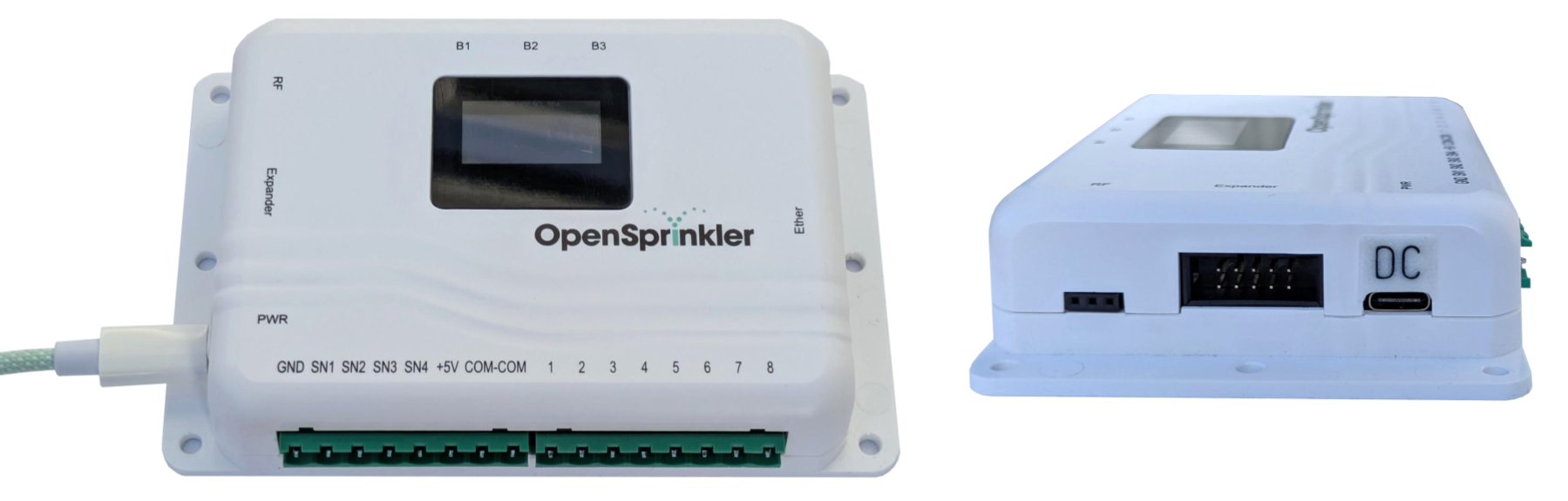
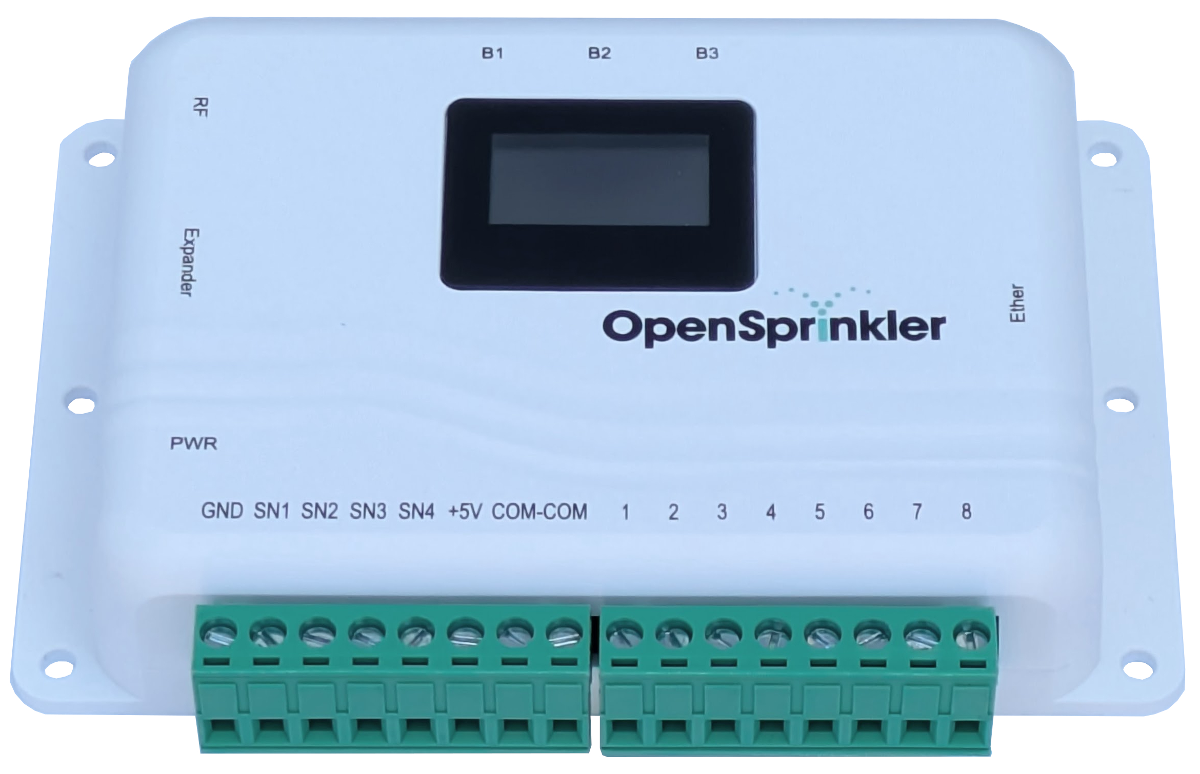
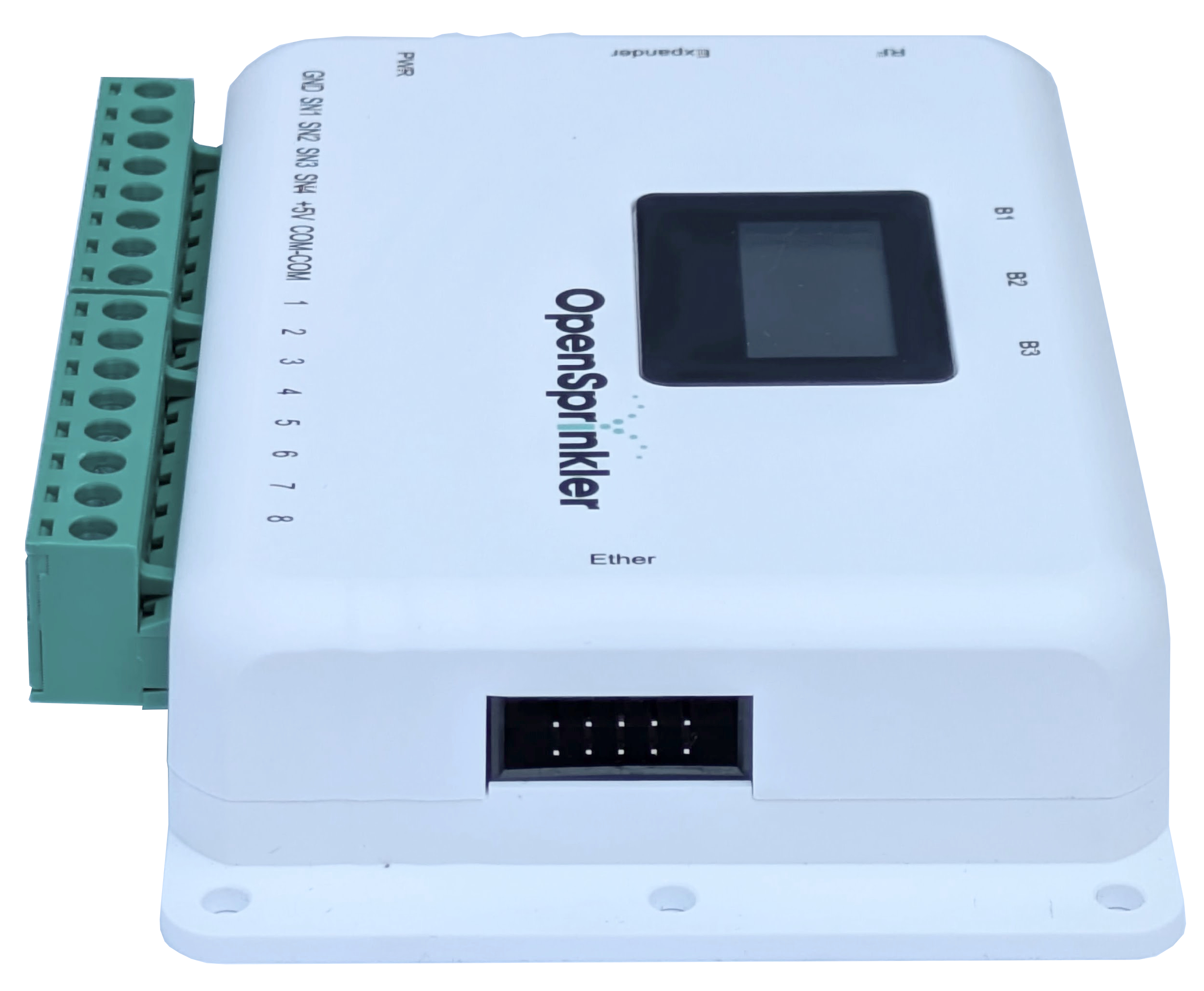
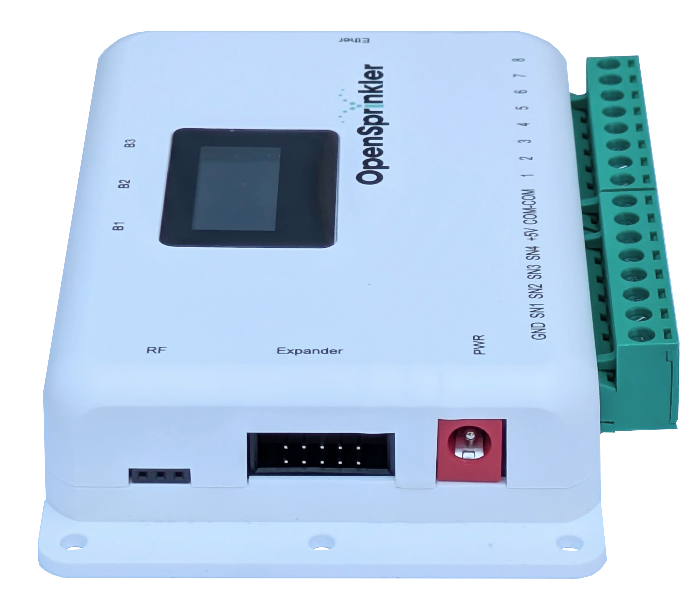
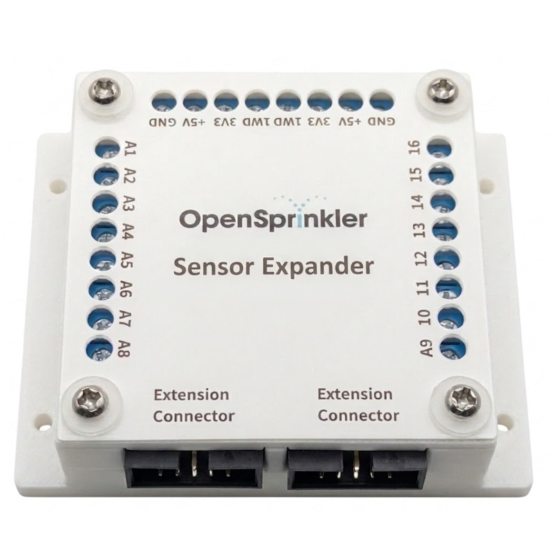
Introducing the OpenSprinkler Sensor Expander—our upcoming product that provides 16 channels of analog sensor inputs, allowing your OpenSprinkler to interface with a wide variety of external sensors and automatically adjust your programmed water times based on real-world conditions. Below are two sneak peek photos of this new expander.
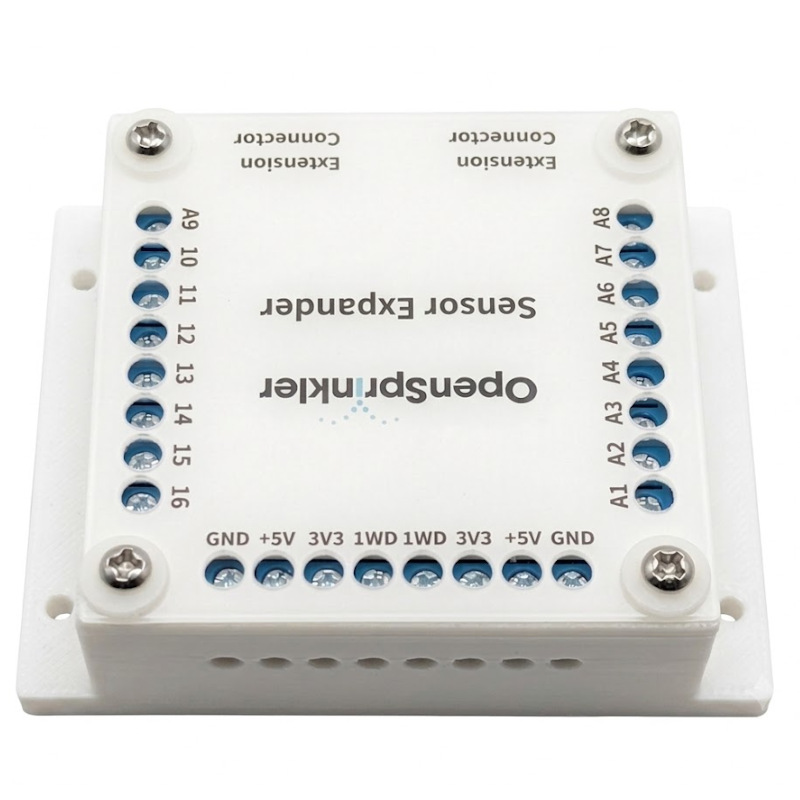
Main Features:
- 16 Analog Sensor Inputs: Powered by four ADS1115 Analog-to-Digital Converters (ADCs), providing a total of 16 independent high-precision analog sensor inputs.
- Dual Voltage Options: Selectable 5V and 3.3V to support a wide range of sensors.
- Easy Expansion: Plugs directly into OpenSprinkler’s Zone Expander connector using the same 2×5 ribbon cable interface. It can be used standalone with the main controller or inserted at any point in an existing Zone Expander chain.
- Hardware 1-Wire Master: Includes an on-board 1-Wire Master controller to enable future support for 1-Wire sensors, such as the DS18B20 temperature sensor (firmware support coming soon).
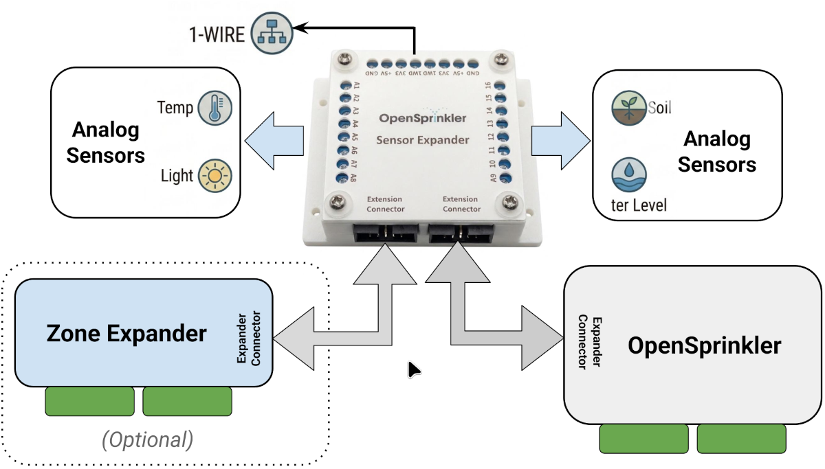
Below is an illustration of the Sensor Expander and how it connects to the OpenSprinkler main controller and (optionally) your Zone Expanders.
Firmware Support
We are actively working on finalizing OpenSprinkler firmware 2.2.1(5), which will be the first release to support the Sensor Expander. Below are several screenshots showing the new firmware user interface in action. We are currently accepting pre-orders, with a targeted shipping date of late-July 2026.
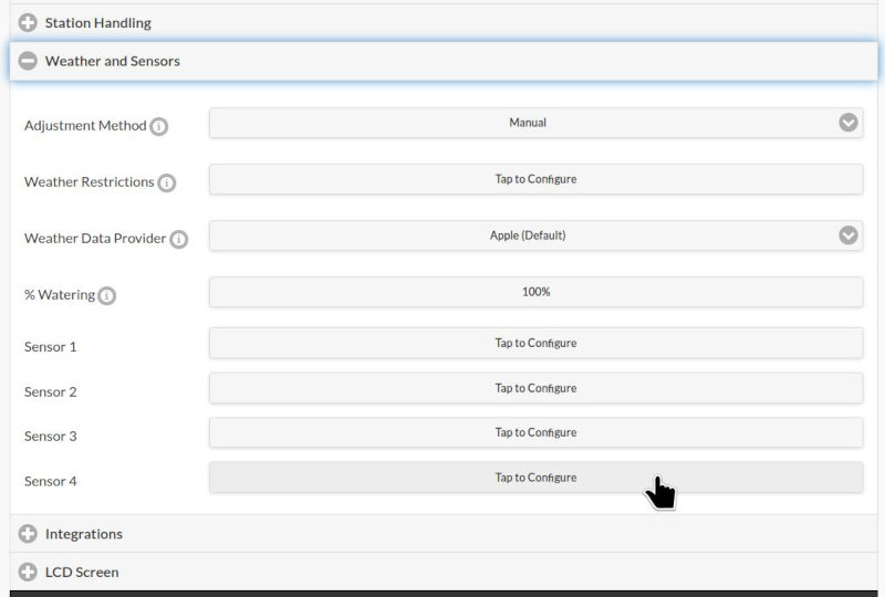
Edit Sensors Page:
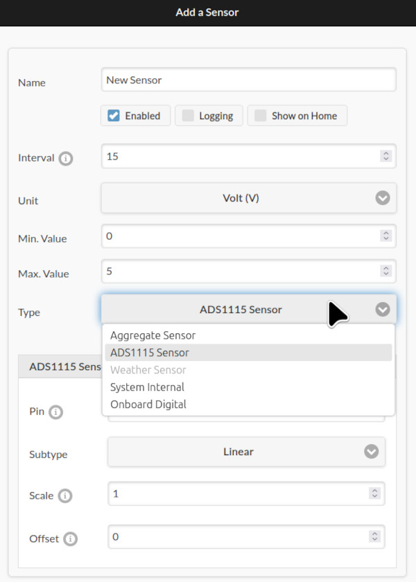
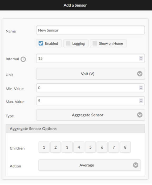
The Sensor configuration interface lets you create a new sensor or edit an existing sensor by providing a custom name, sampling interval (e.g., every 15 minutes), physical unit, min/max clamping values, and sensor type. Currently supported sensor types include:
- ADS1115: For sensors connected to the expander’s analog inputs. Includes three sub-types:
- Generic Linear: Define custom linear parameters (scaling and offset) that map raw ADC voltage to sensor value.
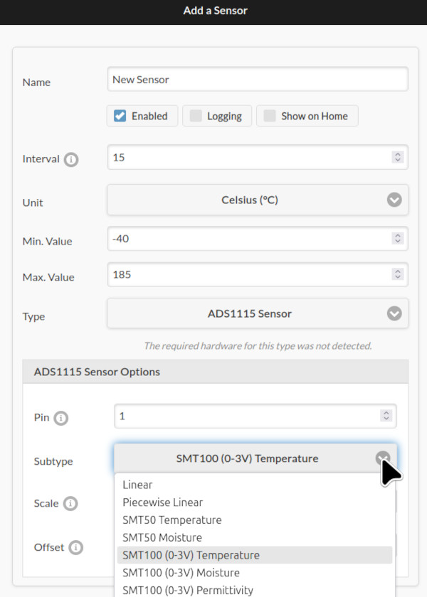
- Baked-in Types: Pre-configured for known sensors (e.g. SMT50 and VH400), with scaling and offset parameters taken directly from the sensor datasheets.
- Piecewise Linear: The most flexible type, supporting non-linear mapping with up to 8 sample points.
- Generic Linear: Define custom linear parameters (scaling and offset) that map raw ADC voltage to sensor value.
- Aggregate Sensors: Combine up to 8 “child” sensors and aggregate their data using operations like
Average, Min, Max, Median. This is useful for example, when you need to average or denoise readings from multiple soil moisture sensors. Aggregate sensors can themselves be children of other aggregate sensors, allowing flexible hierarchies. - On-Board Digital Sensors: Allows you to programmatically link the controller’s internal digital sensors (e.g., rain, soil) to the new Sensor interface. Normally, on-board sensors affect watering on a per-zone basis (via each zone’s ‘Ignore Sensor’ flag). By routing them through the Sensor interface, you can use them in program-level adjustments.
- System Internal Sensors: Monitor metrics like available Heap size and Flash size. Combined with logging, this lets you track the microcontroller’s resource usageover time.
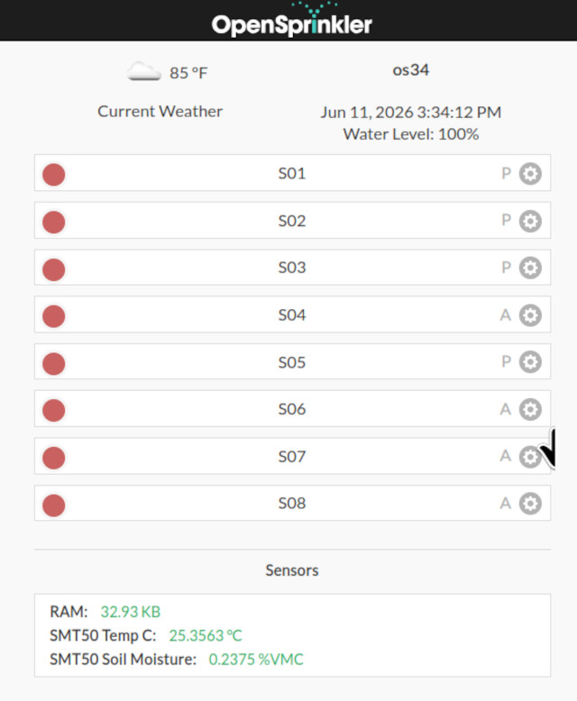
Note: Firmware 2.2.1(5) supports up to 64 sensors total, each with configurable parameters such as logging and the option to display on the home page, as shown below.
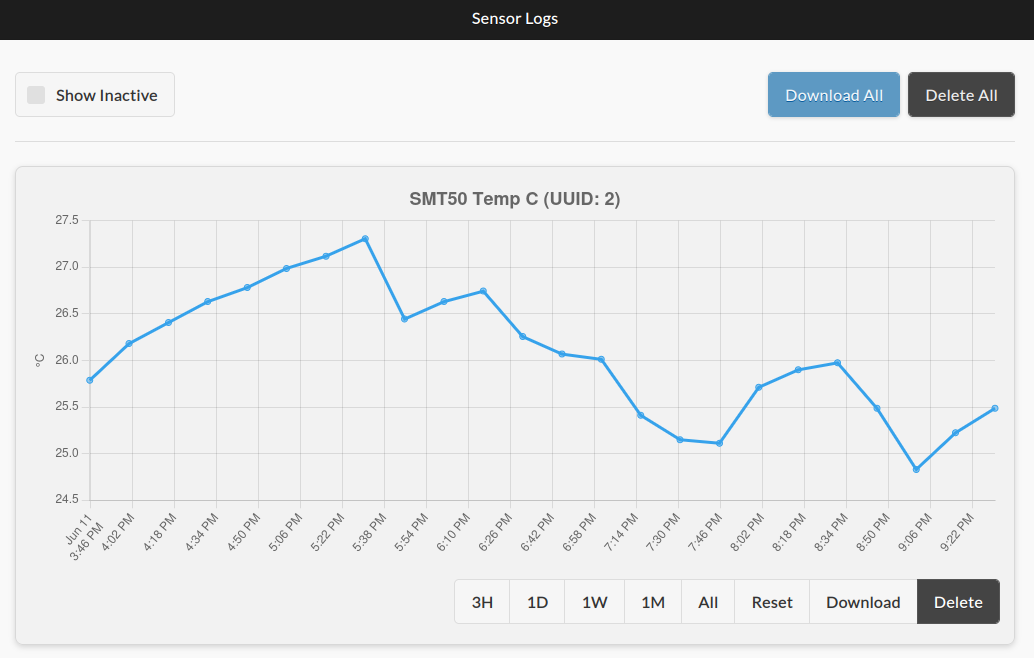
Sensor Logs Page:
The Sensor Logs page displays logged data from all active sensors that have ‘Logging’ flag enabled. You can select different time windows to zoom into specific periods, download the logs as .csv files for external analysis, or delete the logs of individual sensor. A “Show Inactive” checkbox lets you view logs from disabled or previously deleted sensors.
Sensor Adjustments in Edit Programs Page:
The Edit Programs page now includes a new ‘Sensor Adjustment‘ section. It lets you define how the program’s water times should be modified based on the value of a selected sensor. For example, reducing watering when soil moisture is high, or increasing it when temperature is warm. You can use any sensor as input, including an Aggregate Sensor that combines readings from multiple sources.
In this interface, you can select a sensor and configure a custom Adjustment Curve using up to 8 sample points, defining how sensor readings translate into watering percentages. The adjustment curve is visualized in real-time, with the current sensor value shown as a green dotted line for reference.
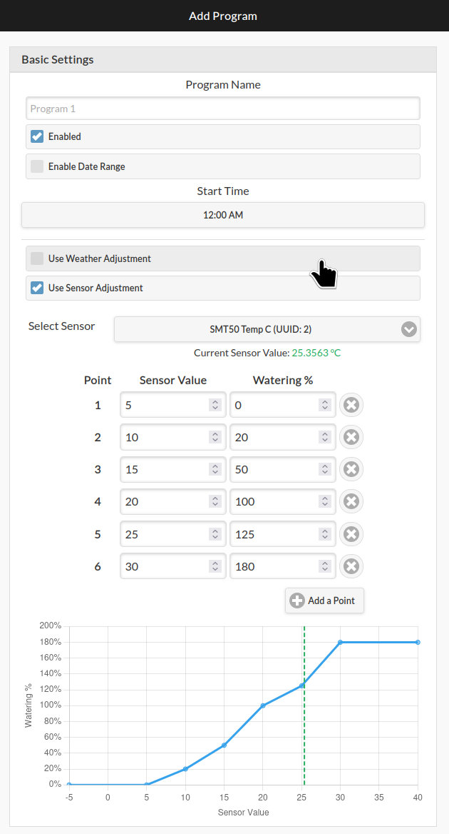
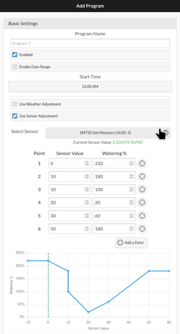
Sensor Adjustment works alongside the existing Weather Adjustment feature. The program’s final water time is multiplied by both the sensor-based percentage and the weather-based ‘watering level’.
Other Firmware Features:
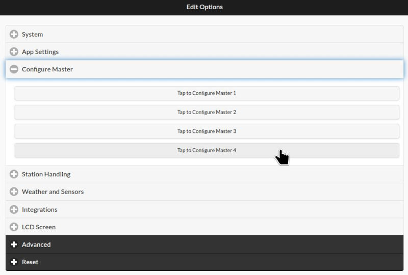
Beyond Sensor Expander support, firmware 2.2.1(5) brings several additional enhancements, including support for up to 4 Master Zones (previously 2), and up to 4 on-board digital sensors on hardware v3.4 (previously 2).
FAQ:
Q: What are some example use cases for the Sensor Expander?
A: The Sensor Expander is particularly useful when you want to modify watering times based on real-world sensor readings — for example, reducing watering when soil moisture is high, adjusting for temperature and evaporation, accounting for ambient light levels, or stopping irrigation when a water tank runs low.
Q: Which OpenSprinkler hardware is compatible with the Sensor Expander?
A: The OpenSprinkler v3 family (v3.0 through 3.4) is compatible. The Sensor Expander uses the same 2×5 ribbon cable connector as the v3 Zone Expanders.
Note that OpenSprinkler v2.3 and OpenSprinkler Pi (OSPi) are NOT compatible with the Sensor Expander. However, recent versions of OSPi (v1.5 and v2.0) feature two on-board ADS1115 chips, providing 8 channels of analog inputs out of the box when updated to firmware 2.2.1(5).
Q: When will the Sensor Expander be ready to ship?
A: We are taking pre-orders now! Shipping is expected to begin in late-July 2026.
Q: What types of sensors are supported?
A: Most analog sensors that operate on 3.3V or 5V logic are supported. Popular examples include the Truebner SMT50, SMT100, Vegetronix VH400, and many resistive and capacitive moisture sensors. The Generic Linear and Piecewise Linear sensor types provide flexibility to support virtually any analog sensor by configuring custom mapping parameters.
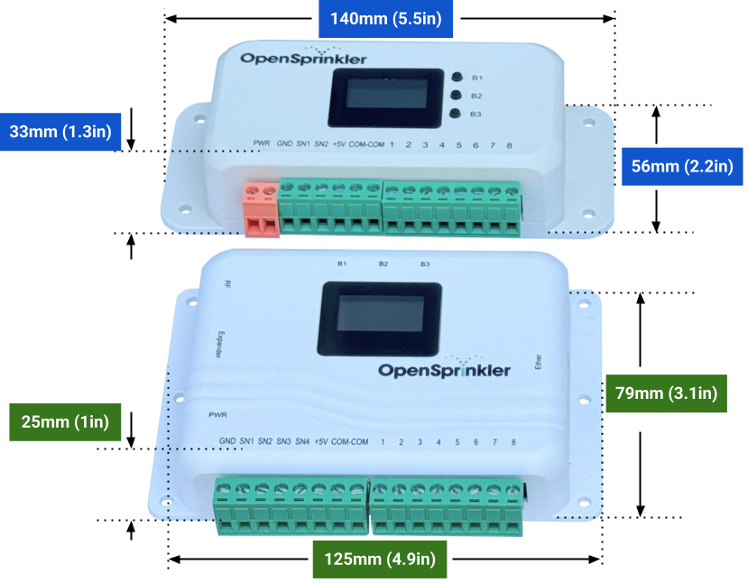
Q: What’s the size and weight of the Sensor Expander?
A: The Sensor Expander measures 80mm × 65mm × 30mm (3.15in × 2.56in × 1.18in) and weighs 75g (2.65oz).
Q: If I use the Sensor Expander, can I still use Zone Expanders?
A: Absolutely! The Sensor Expander works alongside Zone Expanders. They both utilize the same I2C communication bus, meaning multiple devices can be connected on the same chain. You can have one Sensor Expander plus multiple (up to 4) Zone Expanders, in any order along the chain.
Q: Can I daisy-chain two Sensor Expanders to get 32 analog inputs?
A: Unfortunately, no. Each main controller can only support one Sensor Expander. The ADS1115 chip allows only 4 unique I²C addresses, and our Sensor Expander already uses all four, so there is no capacity for any additional. If you require more than 16 analog inputs, you will need to add a second OpenSprinkler main controller with its own Sensor Expander.
Q: Can I connect digital sensors (e.g., rain sensor, flow sensor) to the Sensor Expander?
A: While switch-type sensors (like rain and flow) can technically be connected to the expander, we highly recommend using the main controller’s dedicated on-board digital sensor inputs instead. The Sensor Expander inputs have heavy low-pass filtering and slow sampling rates, optimized for analog measurements rather than fast digital signals.
Flow sensors should NOT be connected to the Sensor Expander. The combination of slow sampling and heavy filtering will cause missed pulses, making accurate flow measurement impossible. Connect flow sensors to the main controller’s on-board sensor inputs.
Q: Can I use custom sensors not in the pre-defined list?
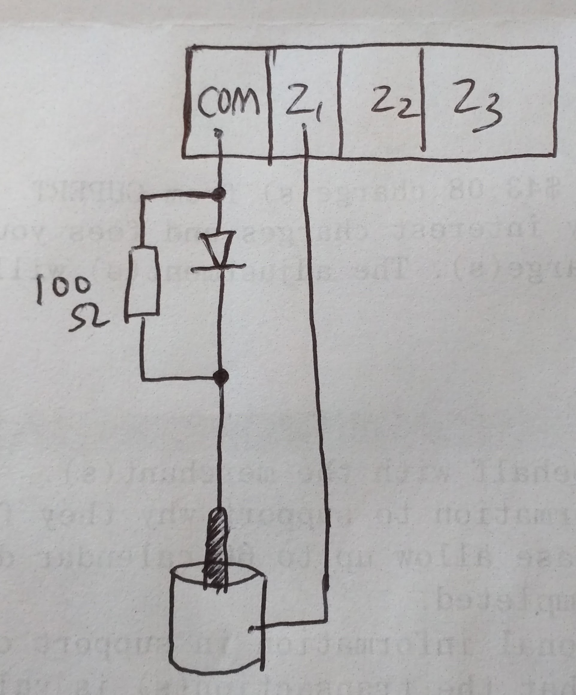
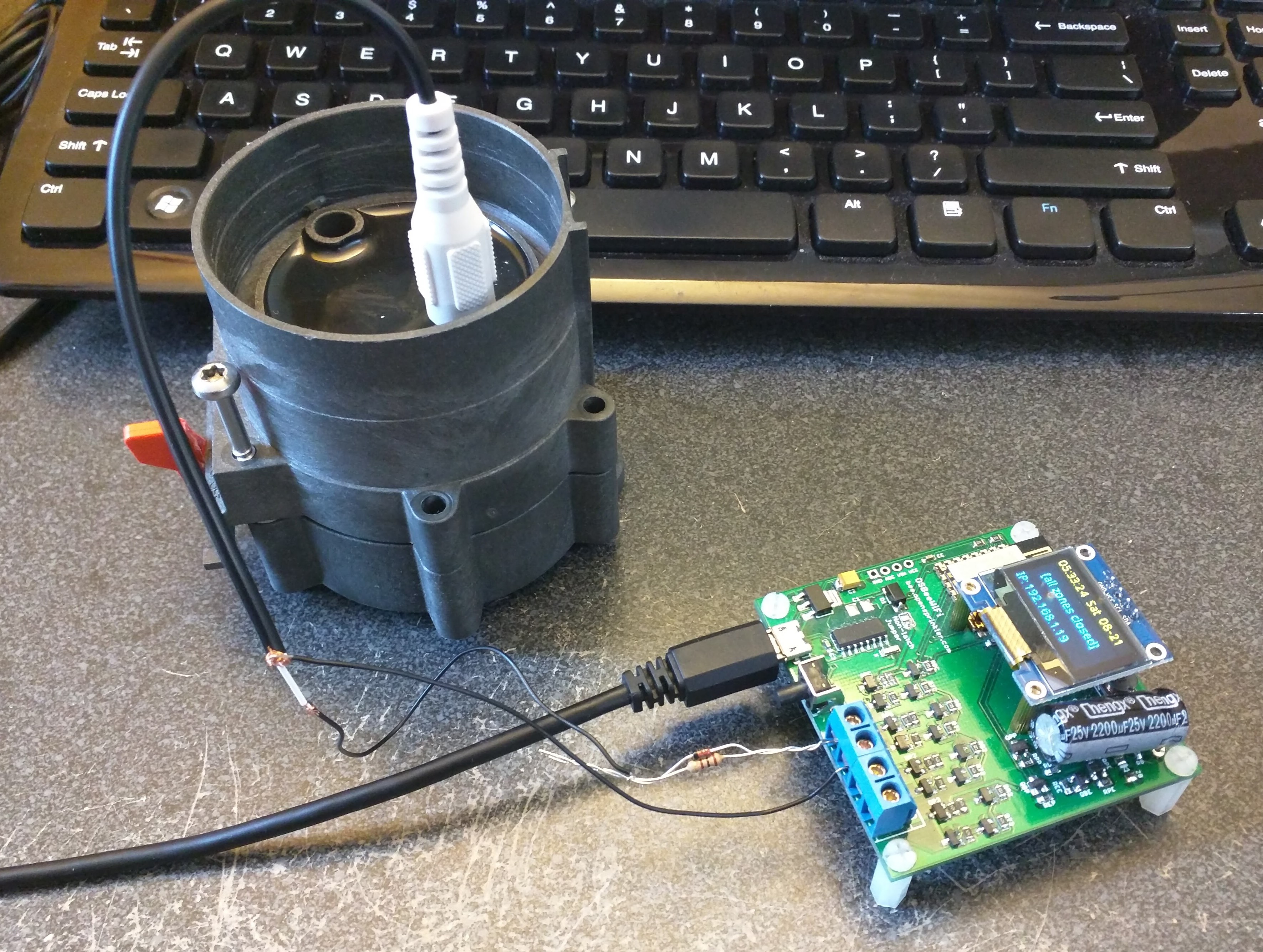
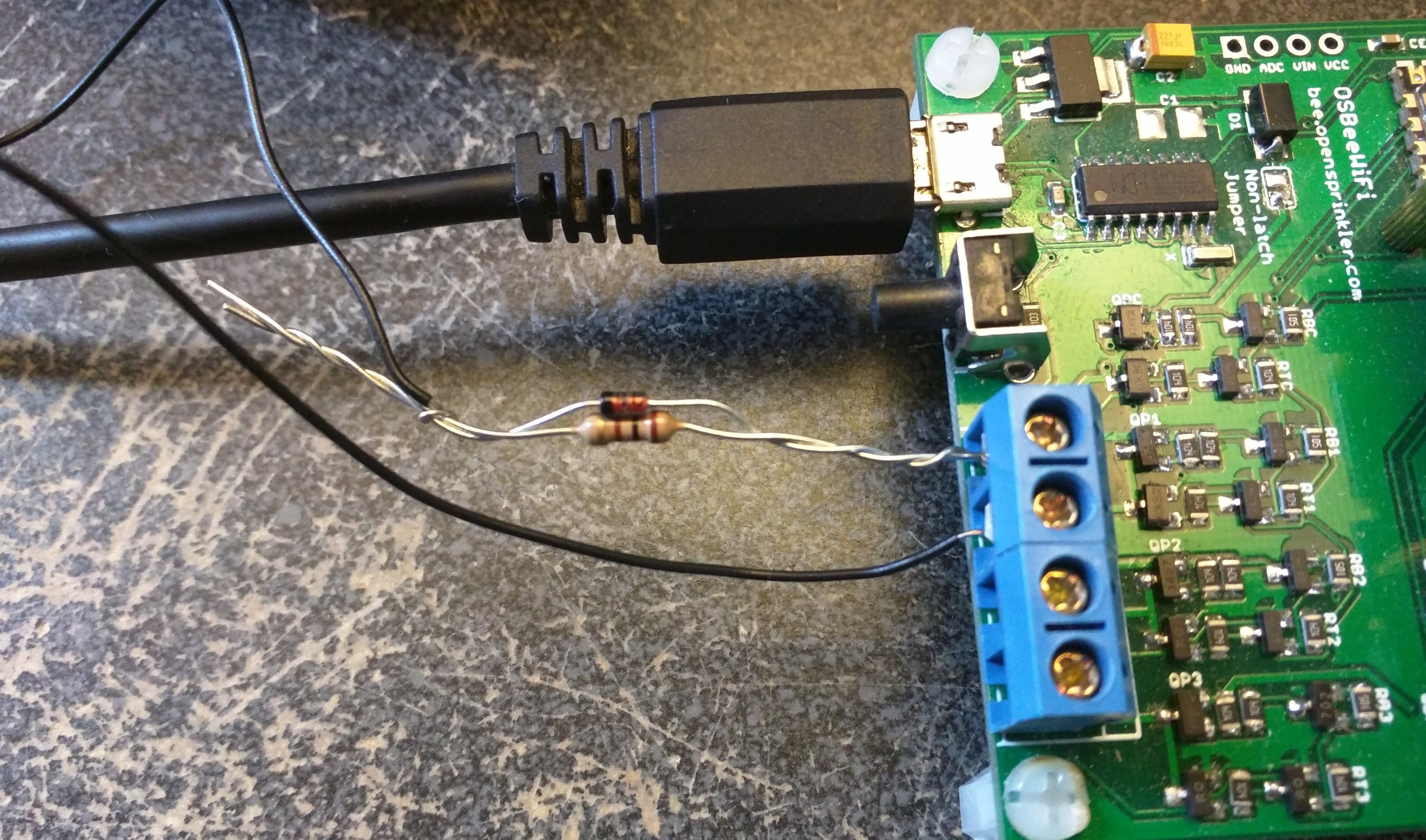
A: Yes! The Generic Linear sensor type lets you configure custom linear mapping (scaling and offset) for any analog sensor. For sensors with non-linear response curves, the Piecewise Linear sensor type supports up to 8 sample points for arbitrary mapping. Your sensor’s datasheet generally provides the formula. Alternatively, an empirical approach is to measure your sensor’s output voltages at known reference values, and use the collected voltage-value pairs to define the Piecewise Linear curve.
Q: What’s the 1-Wire Master for?
A: The Sensor Expander includes an on-board 1-Wire master controller, capable of processing the 1-Wire communication protocol. But firmware support for 1-Wire sensors (such as the DS18B20 temperature sensor) is not yet implemented. We plan to add this in a future firmware update.