OpenSprinkler › Forums › Hardware Questions › Alternate way to power TP-Link with OpenSprinkler v2.3 ?
- This topic has 9 replies, 4 voices, and was last updated 10 years, 10 months ago by
Ray.
-
AuthorPosts
-
June 15, 2015 at 2:32 am #38421
JaansParticipantHi all
So I decided to replace my Hunter X-Core 8 zone outdoors controller with OpenSprinkler v2.3.
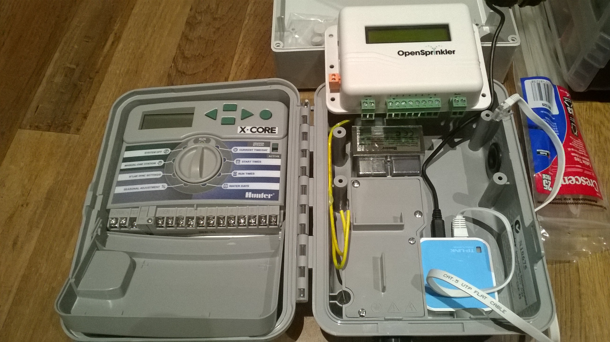
I was planning to use generic IP56 enclosure, but then I realised two things. First was that the Hunter’s 24VAC 1A transformer was perfect (I hadn’t sourced a local suitable transformer yet – actually a bit harder than I thought), and second was that if I removed the Hunter Controller panel (the PCB with terminals, dial and display), the mounting points that it used fits my OpenSprinkler. A picture will explain better – see attached with the Hunter Controller panel removed and placed on left.
To recap my situation, I might be able to completely re-use the Hunter X-Core controller enclosure, the Hunter transformer, fit the OpenSprinkler and also the TP-Link WiFi adaptor (picture a kid smiling if you will). This could be be great.
Then I realised, that to power the TP-Link unit from the OpenSprinkler USB port (using the USB Female A to Male B adaptor) wasn’t going to be possible as it’s simply too big – actually it’s enormous (picture the same kid with a saddened frown now).
I’ve searched extensively and I was not able to find a special USB cable that would be the equivalent conversion (therefore eliminating the need for the adaptor). I also was unable to source an alternative USB adaptor that had a right angle connector that could do the job either.
My thoughts now turn to possibilities of being able to connect to the OpenSprinkler 5v source internally to power the TP-Link WiFi. Alternatively, find some way get 5v DC from the 24v AC transformer that the OpenSprinkler is already connected, if that is even possible.
Hopefully my limited electronics experience isn’t making my consider impossibilities. I would really prefer to be able to reuse the Hunter enclosure and power source configuration, “I just need power schotty”!
Any suggestions would be greatly appreciated.
JaansAttachments:
June 15, 2015 at 9:09 am #38426
JaansParticipantUpdate: I’ve done a trace of the power pins of the USB connnector on the OpenSprinkler PCB and from what I’m able to assess is that both the GND and Vin pins on the USB are connected to the same GND and Vin pads (above the LCD header) without any resistors, capacitors affecting the current or voltage (as far as I can see).
So, now I’m thinking of cutting off the one end of a USB B-Micro cable and connecting the RED and BLACK inner cables (after confirming that they are the GND and Vin leads) and connecting the cable to the pads on the OpenSprinkler.
Is this a bad idea for me-the-ignorant-electronics-tinkerer to be doing some reason?
June 16, 2015 at 5:49 pm #38475
Oasiz37ParticipantIn a similar situation I’ve managed to squeeze in a flexible USB A-to-B adapter USBAF-USBBM-F found at http://www.vpi.us/usb-gender-flex.html, check it out. Still beats me why OS is using such an outdated connector.
June 16, 2015 at 8:15 pm #38489
RayKeymasterWe sell a USB adapter that you can use to power the WiFi adapter from OpenSprinkler’s USB port:
http://rayshobby.net/cart/accessories/acc-usb/usb-fa-mb
you can also buy this from Amazon. But the flexible one that Oasiz37 linked to is more convenient.The reason OpenSprinkler still uses the USB B female connector is that the enclosure is made to fit this type of connector. We could have switched to use microUSB but that would require a re-make of the enclosure. Keep in mind that OpenSprinkler originated from an Arduino-based sprinkler controller, and even now Arduino still uses the same USB connector.
July 9, 2015 at 8:29 am #39149
ZoltánParticipantJaans, I am also planning to replace the exact same 8 zone Hunter controller and I was just measuring the inner size of the housing when I found this thread. I am so happy to see that the TP-Link wifi router fits that small place on the right.
Could you please send us a photo when you finished? Finally, what USB converter did you use? Can the OS case be fitted easily?
Thanks,
ZJuly 11, 2015 at 10:55 pm #39196
JaansParticipantHi Zoltán. I’ve done two of these now and it works like a charm (I cannot thank Ray enough for a solid product and software!).
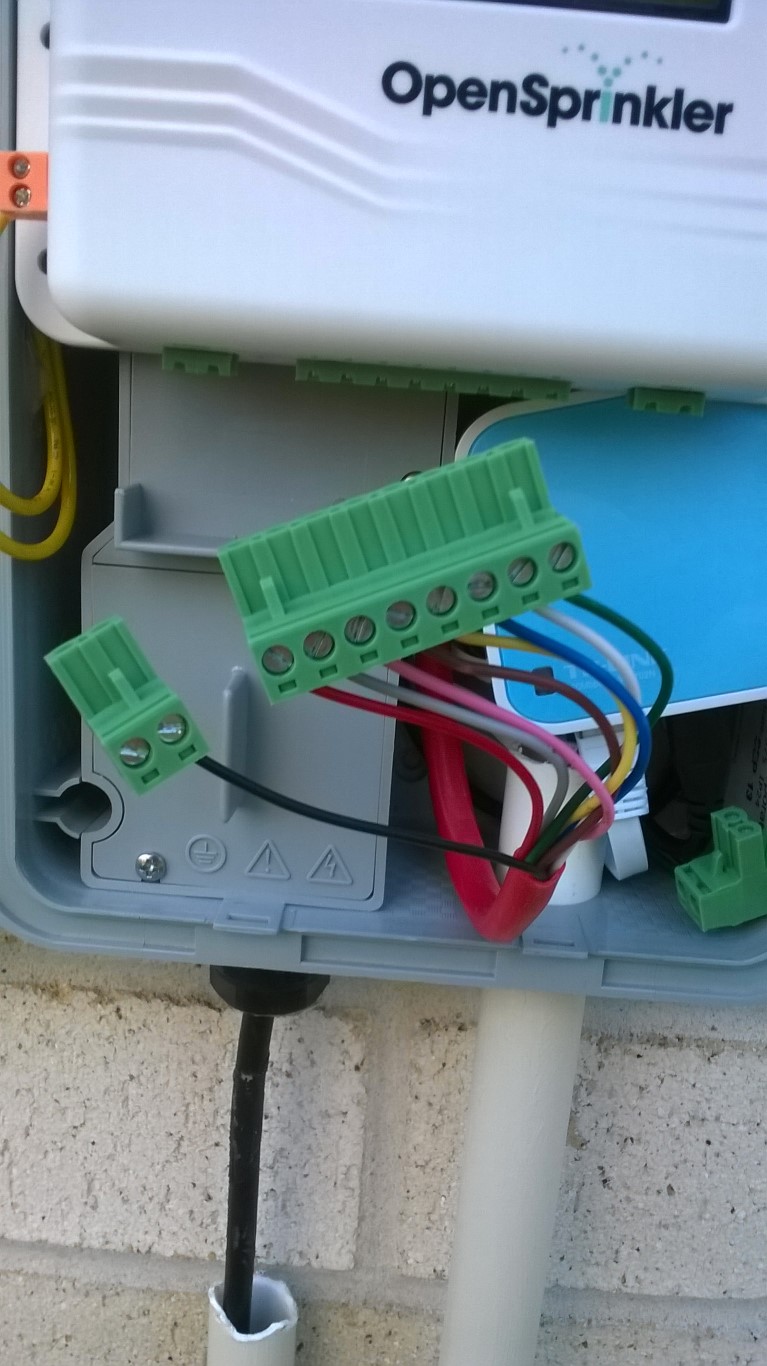
Many sprinkler controllers (at least the ones I’ve come across here in Australia) are externally located and contained. In addition – due to the electrical regulations here – they require approved transformers and housings and connecting them to mains supply is also regulated.
Given that the OpenSprinkler housing is not waterproof (and I don’t think UV resistant) or to be specific is not an IP68 rated enclosure, I need to place it inside an outdoor controller box (not to mention the similar limitations of the associated TP-Link nano unit). This is all generally fine and expected, but it does add additional cost to then either re-locate it indoors or use replacement housings. Also, since every country has their own electrical regulations, it’s impossible for Ray to provide a universal solution with outdoor box and 24VAC power, at least not without having to establish a some sort of local distributor for each regulated country that can then address these requirements for their local market.
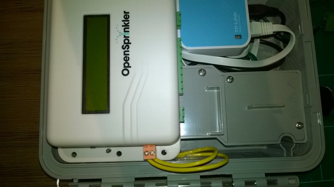
That, and the convenience of doing an in-situ replacement of existing sprinkler systems like this Hunter configuration with an OpenSprinkler unit is therefore ideal for me. I have some older photos attached showing the first rough version where the OpenSprinkler housing was simply screwed onto the same mounting posts as that of the Hunter controller unit, using the included self-tapping screws, onto the “flange” of the OS housing. This does leave an undesirable sharp pointed “danger”, but you can “put a cork over it” or something. In my second build (for a friend – so I don’t have photos here) I pre-drilled a hole next to the existing ones and used a prettier nut-and-bold solution.
You could of course align the existing holes in the OS flange, but for me the positioning of the OS within the box wasn’t ideal then.
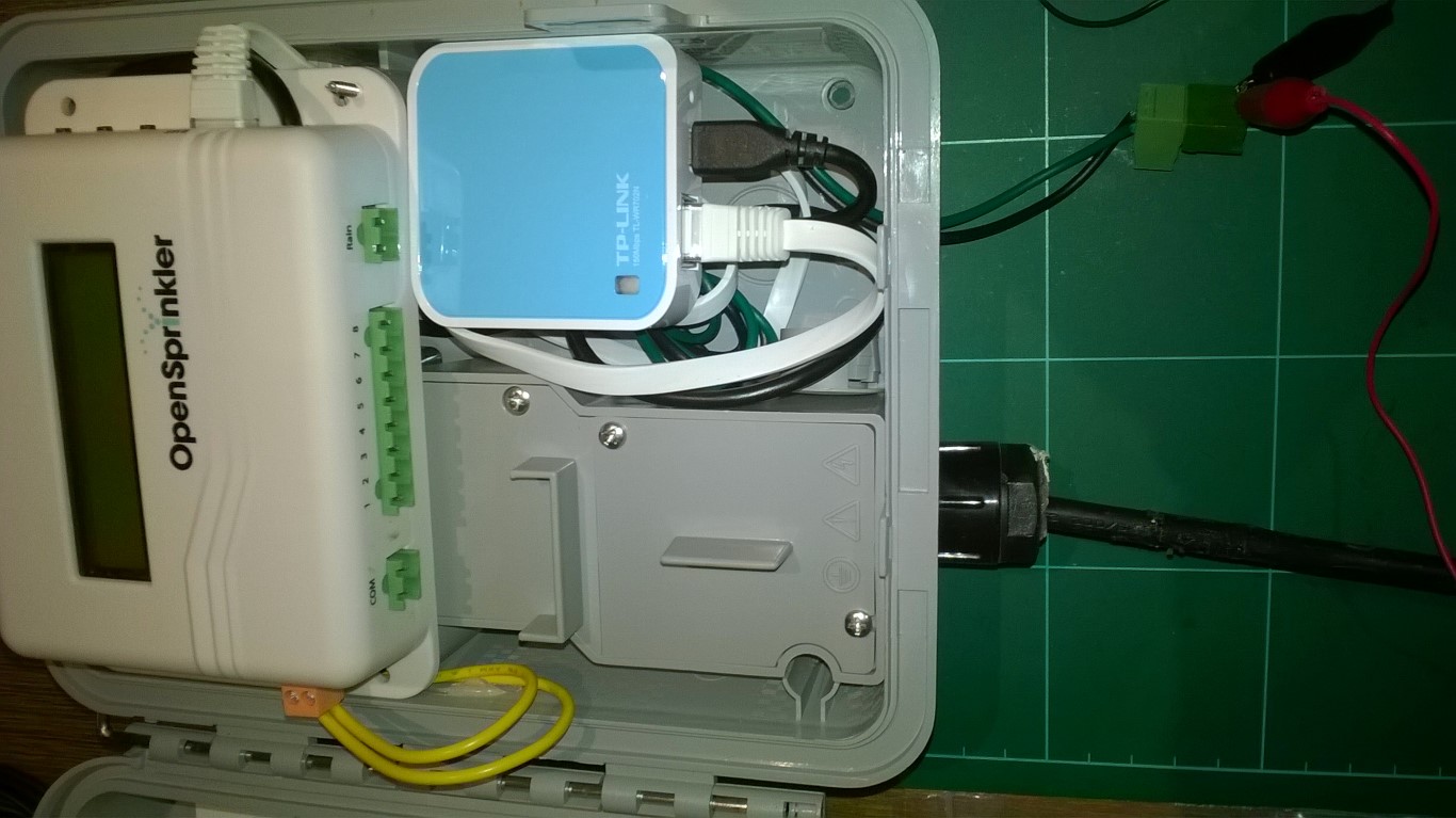
Notice how the nice and flexible flat Ethernet cable (that is supplied with the TP-Link unit) is happy to be shaped around to the back of controller. I’ve even used an existing “notch” on the side of the Hunter box to allow for the Ethernet cable to rest in.
As for powering the TP-Link, my need for re-using the Hunter box and it’s included transformer forced my hand to find an alternate solution. I ended up opening the OS unit (screws on the back) and then soldering a small male-connector (2pin) header onto the OpenSprinkler PCB for the GND and Vin pin holes (it’s just above the LCD connector headers). I then cut a spare USB-Micro cable I had available and soldered a female connector onto the USB cable and heat-shrunk it. I chose a USB cable that was as thin and flexible as I had (surprised at how many I have in my drawer actually O_o).
Given that this is only for power and not USB signally, I’m OK with this. I suppose you could directly solder the cable into these pin holes, but I don’t think is a robust solution if it runs to the “outside” of the housing. You’ll need to use the Red/Black inner wires, but do make sure you manually verify your own cable as I don’t trust the color-coding on face value. This link should be helpful: https://en.wikipedia.org/wiki/USB
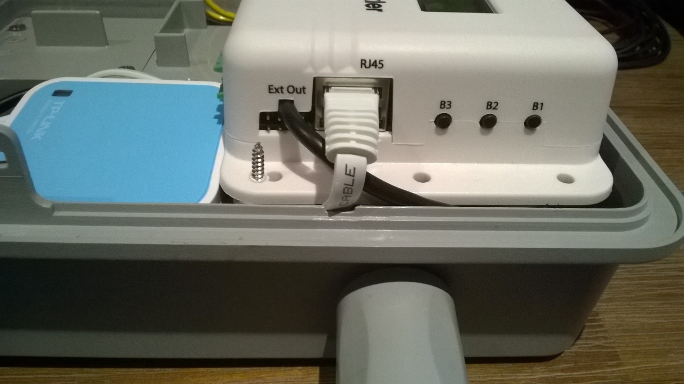
I then plugged the connectors together, and carefully routed the cable around the LCD support post down to the bottom right of the open sprinkler where the connector for additional expansion modules is located. I did this because there is a little notch in the OS housing (for the ext out connector) which allows me to gently exit the OS housing with the USB cable and slip it in behind it. Refer photos. On the other unit, I drilled a small hole in the OS Housing and used a small rubber grommet through which I ran the USB cable to the outside of the OS housing – suggest you add a cable tie to the USB cable on the inside of the housing, to help resist accidental pulls on the cable from disconnecting on the inside. Glue-gun / Silicone is a handy fixing agent for cables and lightweight stuff.
I’m happy with the result and I’m funding it robust, rugged and neat (enough for me anyway).
Do note that the TP-Link has thermal limitations (I think around 40 deg. Celcius) so take that into consideration when locating the unit externally and avoid sun on the Hunter housing if you can.
I’m still working on “interfacing” with the Hunter Solar Sync ET and Rain signals (either directly with the RF signal or the receiver module – but this is a long term project I suspect. Will post if I get somewhere practical with it.
Hope this helps and enjoy!
July 12, 2015 at 2:26 pm #39210
ZoltánParticipantHi Jaans, thanks for your fantastic answer.
Do you think this USB cable would fit that place on the left? http://rbx.hu/startech-usbab1mr-1m-usb-20-a-b-kabel-jobbra-ford-p372810 It needs about 6mm space between the OS and Hunter housings. If it does not fit then I will go with your soldering solution.
Thanks for the warning about overheating the wifi router. My Hunter controller is located on the west side of my house and is directly exposed to sunshine between cca 3-6pm when it is not very hot so I hope it won’t be a problem.
Another big thanks for mentioning the flat UTP cable that comes with the router. I was just going to order one.
Regards,
ZoltánJuly 13, 2015 at 1:48 am #39223
JaansParticipantHi Zoltán.
Using a ruler, from what I could see, I have about 9-10mm available on the left edge of the OS housing and the right edge of the Hunter housing. So in theory it could fit. I’m sure you are aware you still need to convert the other end of the cable’s USB A connector to a Micro-B plug to connect to the TP-Link Nano unit (i.e Micro-B plug is the male end – though the USB standard uses plug/receptacle terms instead of male/female). There is space behind the OS (once mounted onto the posts) to “bury” converters/adapters/gender-benders.
I have noticed that with USB B connectors, they don’t seem to go completely flush when mating so you might find that it sits a little proud of the OS sprinkler receptacle, how far is anyone’s guess. You may need to try it out to know for sure. There is a little play by mounting the OS unit to the Hunter mounting posts a little further to the right thus giving you more room on the left, but note this will shift the same constraints to the RJ45 Ethernet connection, though that cable is so flat and flexible I half suspect you can make it work without causing undue forces onto the OS parts or the cable itself.
My suggestion would be to not mount/fix/screw/glue the OS housing onto the Hunter mounting posts until you’ve assessed your USB connection spacing and balanced it on both ends. Bear in mind that when the Hunter door closes you don’t want it to catch anything or cause you to force anything.
Hope that helps!
July 13, 2015 at 9:36 am #39226
ZoltánParticipantHi Jaans,
Thanks for the dimensions. I decided I order az OS AC model, a TP-Link wifi device and the USB cable above, along with a micro USB converter and I will only modify anything in the housing if needed.
Now, IMHO the weakest point is the wifi router. I do hope the TP-Link stuff does not break my wifi network as it did for many others here and also hope it will not get cooked.
When I finish, my next project is to throw together a RPi based solution that regularly uploads my La Crosse OEM PWS data to Wunderground so I can access my own data with OS. 🙂
Thanks again for all the valuable information!
BR,
ZJuly 13, 2015 at 3:37 pm #39240 -
AuthorPosts
- You must be logged in to reply to this topic.
OpenSprinkler › Forums › Hardware Questions › Alternate way to power TP-Link with OpenSprinkler v2.3 ?