My unit (old 2.1 version) recently stopped working. I had to find workaround. So i connected relays to GPIO on raspberry and everything is working fine with opensprinkler software. I have zone expander 2.1 (with shift register) and it should be possible to connect it instead of relays. I tried to analyse Eagle PCB schema of zone expander but no success and i do not want to fry my expander.
What I find out
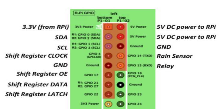
– GPIO schema from user manual
– board 1.0 pinout schema https://github.com/rayshobby/opensprinkler/blob/master/OpenSprinkler%20Pi/docs/v1.0/diagram_expansion_board.jpg
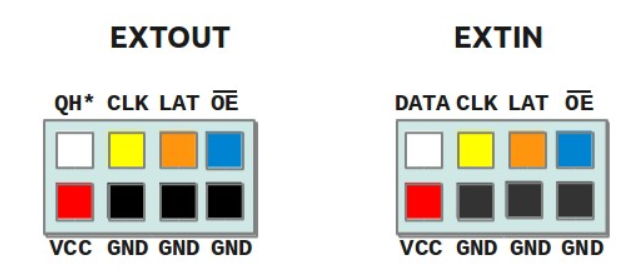
So believe I should connect GPIO 17 (OE) to EXTIN (OE), GPIO 21 (DATA) to EXTIN (DATA) , GPIO 22 (latch) to EXTIN (latch), GPIO4 (Clock) to EXTIN (Clock) , GND from raspberry to GND of expander.
Question is – am I right and those connections are correct? What I should connect to VCC of expander ? Wire from 24V AC? What concerns me that in PCB expander version 2.1 3 GND pins are not connected so maybe board 2.1 pinout is different?
Thanks for advice.
Regards
Piotr
.