OpenSprinkler › Forums › Hardware Questions › OpenSprinkler › Driving 14 valves or 12 + Main Pump from OS 3.0
- This topic has 17 replies, 3 voices, and was last updated 4 years, 6 months ago by
nickarsow.
-
AuthorPosts
-
December 1, 2021 at 1:17 pm #71770
nickarsowParticipantHi guys,
I have an interesting idea which work perfect.
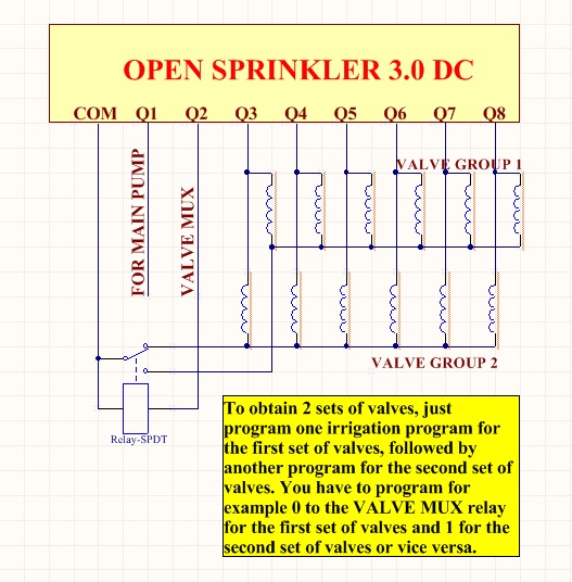
One can drive more than 8 valves with a single OS 3.0. Look at the attached picture as it describes everything.
With 2 relays, you can drive 20 valves in 4 programs, etc, etc….If you have questions, don’t hesitate to ask.
Best regards
NickAttachments:
December 1, 2021 at 7:47 pm #71777
RayKeymasterWow, that’s a very clever idea. By splitting the zones into two sets, one set of which drives relays that supply ‘com’ wire to the other set of valves, you can drive a large number of zones. Thanks for sharing! It also sounds like an interesting math problem to find out how to split the zones to achieve the maximum number of valves.
December 2, 2021 at 6:19 am #71783
nickarsowParticipantHi Ray,
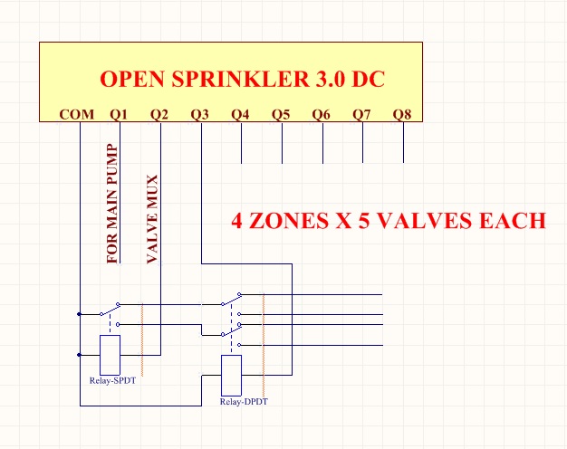
Attached is an example for 4 zones x 5 valves each = 20 valves total.Btw, do you know the time needed for charging the boost capacitor to fire a valve?
I need it to decide the program cicles.BR
NickAttachments:
December 2, 2021 at 12:43 pm #71788
RayKeymasterThe time for boosting depends on the input power supply voltage. The booster circuit itself has been configured to boost to ~21VDC (so even if the booster is turned on indefinitely it won’t go past 21V). The higher the input power supply voltage, the faster it is to reach that limit. With 7.5VDC input (the default), it probably will take 500ms to 750ms. You can leave the boost time to 1000ms if you want to make sure it reaches the maximum.
December 3, 2021 at 9:29 pm #71796
Ryan TurnquistParticipantNick,
Very cool idea! I have a question. Would it be possible to make the relay (Q2 in first post) the master for the valve group 2. Therefore one program can have all the valves run where valve group 1 uses only Master Pump (Q1) and valve group 2 uses Master Pump (Q1) and master relay (Q2)?
Thanks
RyanDecember 4, 2021 at 8:42 am #71798
nickarsowParticipantHi Ryan,
MasterPump on Q1 is separate from all other outputa, so you can use with any program and valve. Additionally, you can wire a valve in parallel to Master Relay Q2, but this valve will work only when Q2 is in ON position simultaneously with the Relay Q2. So, one valve group will have 7 valves, and when Relay Q2 switches OFF, the other valve group will have 6 valves you can operate with. The problem is that Valve 2 must be ON during the program of the first set of valves.1. Master Q1 is a MasterPump Q1. Relay Q2/Valve 2 = ON, the other valves Q3 to Q8 – according your program. The problem is that Valve 2 will be ON during this program;
2. Master Q1 is a MasterPump Q1. Relay Q2/Valve 2 = OFF, the valves Q9 to Q14 – according to your second program.BR
NickDecember 10, 2021 at 1:59 am #71840
nickarsowParticipantHi Ray,
I noticed a strange OS 3.0 behavior while experimenting with relays:
My 8 relay board has optoisolators, which sink about 10mA/channel. So, I decided to use the 5V ( marked VIN on the OS 3.0 board ) to power the optoisolators. This works fine, but when I decided to set the BOOST time to 0ms, it refused to save and always shows 320ms.
I want to disable the booster, because it is not needed for relays.
What I have to do for the purpose? I can disable it in the hardware, but don’t like to cut traces.BR
NickDecember 13, 2021 at 8:47 am #71855
RayKeymasterIt could be a UI problem. You can try the following approach to use buttons to edit the option value:
– remove power from OpenSprinkler, then power it back on, as soon as you see the OpenSprinkler logo, press and hold the third pushbutton (B3) and continue holding until it shows ‘Setup Options’.
– click B3 as many times as you need until it goes to the ‘Boost Time’ option. Then use B1 or B2 to change the value
– when you are done, please press and hold button B3 again until the controller reboots itself.If this still doesn’t work, it’s likely a flash memory problem. You may have to do a factory reset. Before factory reset, please save a copy of your configurations so you can recover the settings later. Factory reset and import/export configurations are all explained in the user manual.
December 13, 2021 at 1:56 pm #71857
nickarsowParticipantHi Ray,
It worked using the buttons. Now boost time shows 0.
Thanks.
BR
NickDecember 29, 2021 at 1:05 pm #71915
nickarsowParticipantHi Ray,
I have a question:
I have a 16 port I2C expander PCF8575 board. Can I use it instead the factory baseboard.
What I mean is to connect it to the 2×6 pin connector ( JP1 ), pins 3 ( SDA ) and 4 ( SCL ).
The factory baseboard has PCF8574TS, with addresses A0=0, A1=1 and A2=0. I can assign the same address to PCF8575 expander board.
Shall Open Sprinkler recognize the expander and how – like ports 1 to 16 or like ports 9 to 24?
My Open Sprinkler is DC V3.0, FW 2.1.9Best regards
NickDecember 30, 2021 at 9:23 am #71924
RayKeymasterThe easiest way is probably to configure your PCF8575 as an expander, i.e. on zones 9-24. The reason is that this is already in the design of an older version of OS expander. The hardware design files are here:
https://github.com/OpenSprinkler/OpenSprinkler-Hardware/tree/master/Expander/3.0/DC
look for the exp30dc one (you will have to install EagleCAD to view the files). The expander I2C address starts with 0x24 (i.e. A0=1, A1=0, A2=0). You can add up to 4 expanders (0x25, 0x26 and 0x27). The particular design of expander 3.0 uses a lot of components (it uses a PNP transistor per channel for logic inverse, because PCF8575 has persistent internal pull-up so it defaults to high on each output, and the PNP transistor reverses that to default low).So the short answer is that yes you can connect PCF8575 as an expander. This way you existing 8 zones are usable and you get 16 additional zones.
If you can get a PCA9555 board, though, the circuit can be a lot simpler. That’s what expander 3.1 DC is based on.
December 30, 2021 at 1:35 pm #71927
nickarsowParticipantHi Ray,
Thanks for the explanations. I had already converted the Eagle files to Altium as I’m designing using Altium Dsigner.
The question I asked because I thought to use my OS 3.0 without the MOSFET drivers, but with an additional ESP32 board with optoisolated inputs and relay outputs.
I’m thinking to use this combination because I have to manage filling the water tanks from a well. This needs constant monitoring of the tank levels and the well water level.
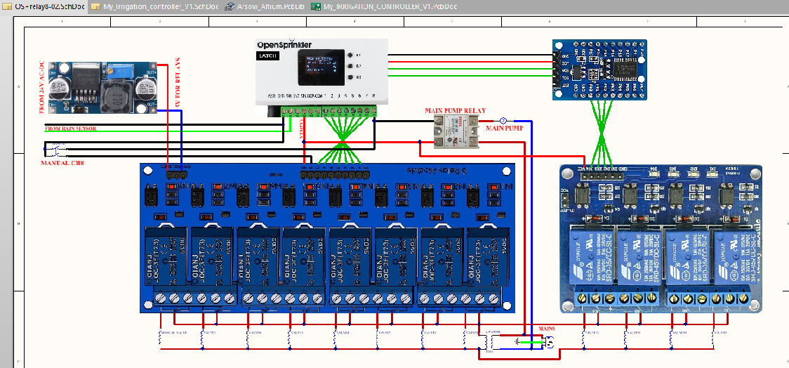
I have already tried to drive opto isolated relays ( active low ) using the OS baseboard, but as the optocouplers accept 5V, I used a bit different approach as you can see from the attached drawing. I’m using VIN power instead COM.
But anyway, it looks like I can remove the OS baseboard without any problems and use the PCF8575 expander board to drive outputs from 9 to 24 without using zones 0-8. Correct?BR
NickAttachments:
December 31, 2021 at 9:23 am #71933
RayKeymasterThere is one small problem about removing the baseboard: the firmware will not be able to detect the baseboard and using its I2C address to decide which type of baseboard it is, and will consequently default to AC driver board (instead of DC in your case). The only issue with this is that it won’t engage the boost converter to generate the boosted voltage. If you don’t need the boosted voltage, this is ok. Pretty much the only difference between AC driver board and DC driver board, in terms of software operation, is the boost converter.
December 31, 2021 at 10:42 am #71934
nickarsowParticipantPerfect, that’s exactly what I need. I don’t need the booster voltave at all.
Btw, which address I have to assign to the PCF8575 expander board?
ThanksJanuary 1, 2022 at 3:09 pm #71942
RayKeymasterExpander I2C address starts from 0x24. See my post 71924 above.
January 5, 2022 at 11:02 am #71965
nickarsowParticipantHi Ray,
I configured the PCF8575 expander board the same way as your OS Expander – address 0x24, Vcc=EVIN from OS expander connector. I added a RED LED with 220R series resistor to test 8575 outputs. The schematic is the same as of the exp30DC.
There is a strange problem:
When I start the OS along with the expander, all expander outputs are H, which os OK. Then I force the ZONE9 for 10 seconds and the LED goes ON, but when the 10s period is over, the LED doesn’t goes off?! The software says it is off, but it is not.
The other issue is that just ZONE09 ( first zone of the PCF8575 ) is “working”, the others not.
Any idea what could be the problem?BR
NickJanuary 7, 2022 at 1:46 pm #71991
RayKeymasterHmm, I am not sure. When using PCF8575, as I mentioned above, since it uses weak pull-up by default all channels are HIGH at start-up, so what I did was to use a PNP transistor per channel to reverse the logic, such that at startup the output becomes low. For this to work I think you will need a pull-down resistor at the output, otherwise the output will be in high-impedance state instead of low.
January 9, 2022 at 2:50 am #72010
nickarsowParticipantHi Ray,
I tried both weak and strong pull-down at the outputs, but the result is the same.
Tomorrow I’ll try to read and store the I2C data stream with my Saleae Logger and will feedback.
The Saleae can read and decode I2C stream and I’ll try to find out what is going wrong.BR
Nick -
AuthorPosts
- You must be logged in to reply to this topic.
OpenSprinkler › Forums › Hardware Questions › OpenSprinkler › Driving 14 valves or 12 + Main Pump from OS 3.0