OpenSprinkler › Forums › Pictures and Creative Use › Indoor watering system
Tagged: h driver
- This topic has 6 replies, 3 voices, and was last updated 9 years ago by
Peter.
-
AuthorPosts
-
January 31, 2016 at 6:29 am #41423
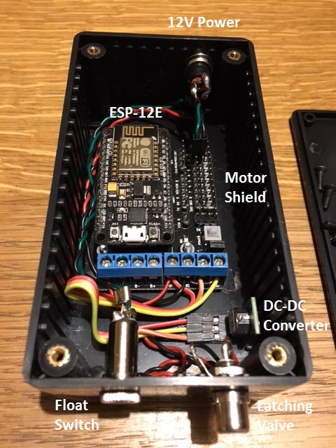
PeterParticipantSo here is a project that I got up and running last year. I have an indoor watering reservoir (one of the Claber Oasis units with a latching valve) that I wanted to drive from my OSPi to get better control over water cycles and also control remotely.
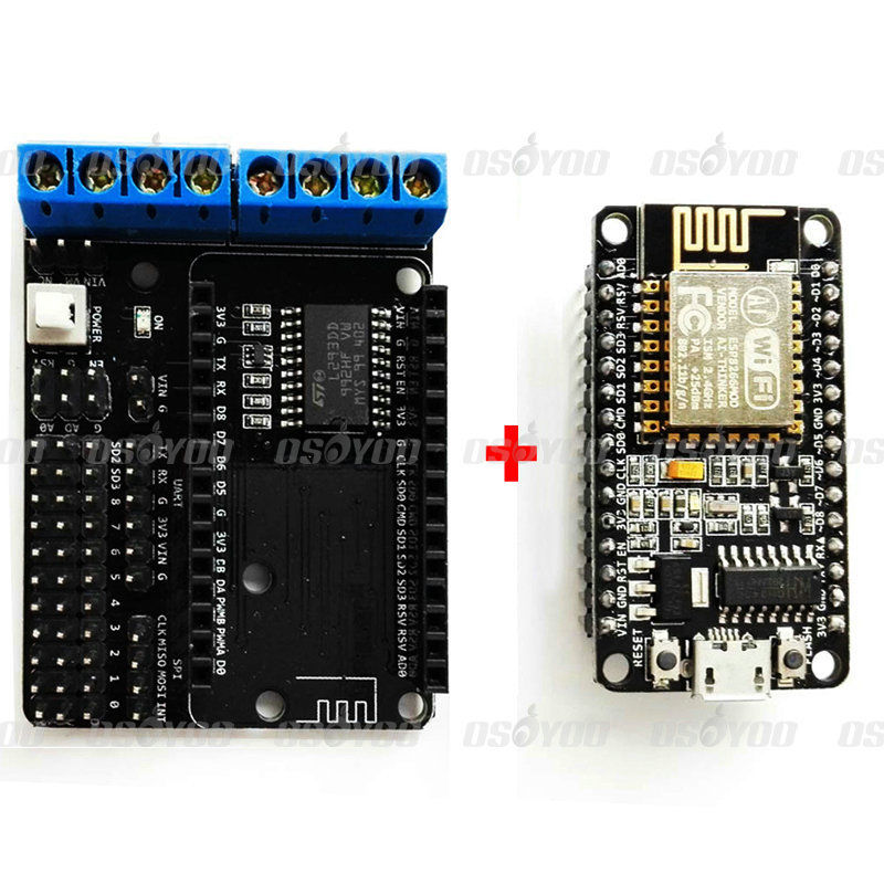
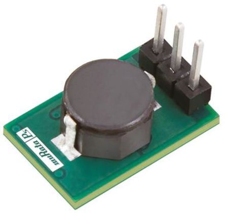
On the hardware front, I took off-the-shelf components and built around an ESP8266 ESP-12E microcontroller (with WiFi) together with a L293D Motor Drive Expansion Shield to drive the latching valves of the Oasis. I also added a simple float switch to let me know when water level was low and powered the unit with a 12V DC transformer feeding the valve and a Murata DC-DC Converter to give 5V for the electronics.
On the software front, I piggybacked onto the Remote Station functionality and wrote a simple ESP8266 program to process the /cm (open/close valve) and /jo (get options) commands that my OSPi Firmware and App sends out. I also added modules to give nntp time and notifications via PushOver when water level is low.
I looked at battery power for this but the ESP8266 is always listening on the wifi and draws quite a bit of current. I couldn’t see a way to power down into sleep mode and so it’s tethered to a power socket.
February 3, 2016 at 1:36 am #41450
RayKeymasterCool, thanks for sharing. It’s interesting that you took the approach of using an OSPi as the master controller, and ESP8266 as a remote station that listens to the main controller. I was actually thinking that ESP8266 is sufficiently beefy to run the OpenSprinkler firmware hence it can serve as a main controller itself. But your solution makes it more modular.
Regarding the current consumption: I don’t think it’s feasible to power ESP8266 with battery and expect it to last for a long time, unless if the battery is a rechargeable battery and used for backup power only. I would just use a USB adapter to power it (or use a battery pack so that it’s still powered even if there is a power break).
February 3, 2016 at 3:10 pm #41458
PeterParticipantI have an OSPi controller wired up in the garden and wanted a way to include the indoor system into the same UI.
If I was doing this again, I might use the new RPi Zero with a wifi dongle instead of an ESP8266. I could have saved myself the coding and used OSPi firmware on the Zero in remote/gpio station mode. But the RPiZ wasnt out and the ESP + Motor shield was really cheap (~£10). It was also a fun project and having push notification when I need to fill the reservoir is nice.
I think I saw another thread were someone was looking to port OSPi to an ESP8266 but didnt see any results?
February 17, 2016 at 12:04 am #41533
RayKeymasterWell I wouldn’t call it *porting* OSPi to ESP8266, I think it’s just making OpenSprinkler firmware work on ESP8266. Since ESP8266 is now supported by Arduino, it wouldn’t take too much work to adapt the firmware to compile for ESP8266. The main challenge is that ESP8266 has a much smaller set of pins (especially analog pin, which it has only one!) This will involve using I/O expander chip and ADC chip in order to adapt all OpenSprinkler functionalities to ESP8266.
June 23, 2017 at 6:14 am #46880
crossmaxParticipantHi @Peter,
You know that I found your sources very useful, but I ordered a nodemcu with the H driver to have the most compact and robust device.
I have ordered 2 pieces of each, and with them I did not get the driver to work. The outputs of motor A are always 0V.I’ve tried several setups, with shorcut connector (short by VM and VIM), thus can use one power source (must be 4.5V~9V) to complete the drive and control for motor at a time. Also with two power source (9V to motor and 5V to nodemcu). I’ve tested your source code without modifications, and your code with my owns settings that I need to work with my other driver. In this old driver, I need to have only one data line in high state to +9V output, and another line in high state to -9V. More descriptive: GPIO0 high and GPIO5 low to +9V and GPIO0 low and GPIO5 high to -9V.
I dont understand why it fail and it is strange that both drivers are defective.
Am I forget something?Thanks once again.
June 23, 2017 at 10:13 am #46885
PeterParticipant[Apologies if duplicated post – @Ray, forum doesn’t seem to allow attaching .ino files ?]
Hey Crossmax,
Glad the code was useful but sorry to hear that the new hardware is not up and running. Can I check that the motor drive board you have is the same as I have pictured above?
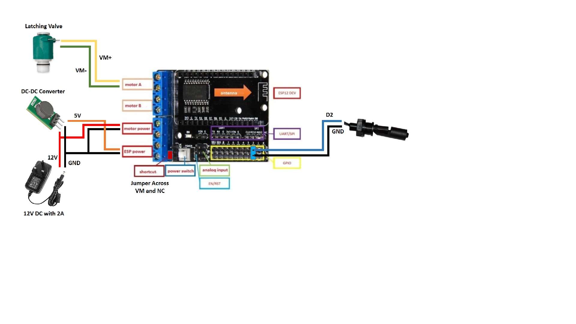
I have attached the wiring diagram that I use but, from your notes above, I’m not sure why your approach hasn’t worked. In my case, I need a higher voltage than the onboard regulator can handle to guarantee latching of the valve so I use a 12V DC supply to drive the solenoid and a DC-DC converter to peel off 5V for the nodemcu. In this configuration, I have the jumper between VM and NC ensuring the power rails are kept separated.
I have attached below a short test routine that I used to check that I could control the motor board. The routine just toggles the Motor A terminals between +VM and -VM on a 2 second cycle in sync with the pulsing blue led on the board. You compile through the Arduino IDE with NodeMCU board selected. This should let you put a voltmeter across the terminals (suggest without valve attached) to check you have the hardware working.
Only other thought off the top of my head is that they may have updated the board and swapped the control pins. Do you have any documentation to confirm pin outs (mine attached) and/or can you follow the traces to see if that might be the issue.
Let me know how you get on and happy to help,
PeteJune 23, 2017 at 10:17 am #46888
PeterParticipantCrosmax, Code for above post as unable to attach .ino file. Rename as tester.ino.
#include <ESP8266WiFi.h> #define VALVE_A_CONTROL_PIN 0 // GPIO0 (D3 on ESP-12E with ESP Motor Chield) #define VALVE_A_ENABLE_PIN 5 // GPIO5 (D1 on ESP-12E with ESP Motor Chield) void setup(void) { Serial.begin(115200); Serial.printf("Setting up pins\n"); pinMode(LED_BUILTIN, OUTPUT); pinMode(VALVE_A_CONTROL_PIN, OUTPUT); pinMode(VALVE_A_ENABLE_PIN, OUTPUT); digitalWrite(VALVE_A_ENABLE_PIN, HIGH); Serial.printf("Starting loop\n"); } void loop(void) { Serial.printf("."); digitalWrite(LED_BUILTIN, 1); digitalWrite(VALVE_A_CONTROL_PIN, 1); delay(2000); digitalWrite(LED_BUILTIN, 0); digitalWrite(VALVE_A_CONTROL_PIN, 0); delay(2000); } -
AuthorPosts

- You must be logged in to reply to this topic.
OpenSprinkler › Forums › Pictures and Creative Use › Indoor watering system