OpenSprinkler › Forums › Pictures and Creative Use › OpenSprinkler 2.1 Garage Door Opener
- This topic has 2 replies, 2 voices, and was last updated 11 years, 1 month ago by
artistikone.
-
AuthorPosts
-
May 26, 2015 at 3:01 pm #37971
artistikoneParticipantI wanted to control my garage door opener via the OpenSprinkler which is mounted on my garage wall but I couldn’t find enough info on the forums on how to do it. After figuring it out and since there are enough posts of others wanting to do it I thought I would post this here for others in case they also want to try it out.
Just a warning – You are working with electricity so please be safe and follow all the standard safety precautions.
I ordered the following parts:
$3 – Some GPIO male to female cables: http://www.amazon.com/gp/product/B00A6SOGC4/
$7 – A 5v DC relay board: http://www.amazon.com/gp/product/B00KTEN3TM/
$1 – A USB Type-B Male to GPIO cable: http://www.monoprice.com/Product?c_id=103&cp_id=10303&cs_id=1030311&p_id=6749&seq=1&format=2
$4 – Some 2-pair 18AWG copper wire long enough to reach your garage door opener. I had some laying around that is like this: http://www.amazon.com/dp/B0002ZGBOC/1. Take two of the GPIO cables and carefully remove the female connector. There is a tiny clip on one side of the connector that you lift up and pull out the cable.
2. For the USB Type-B cable you want to pull out the two wires that provide the 5v DC power. For this specific one the power was on the red cable (which was in pin #1 of the 5-pin GPIO connector) and black (which was in pin #4). There are two black cables so to be sure use a multi-meter set for 5v DC, plug the USB end into your OpenSprinkler (or any USB source) and test them.
3. Take the two female GPIO connectors you removed and put them on the two wires you just pulled out of the 5-pin GPIO connector.
4. With the USB end of the cable- unplugged
attach the red power wire to the VCC pin on the relay board and the black ground wire to the GND pin. This specific board has a jumper attached on the second VCC to JD-VCC pins so make sure that’s connected. You could optionally use a different power source for the board but that’s not covered here.
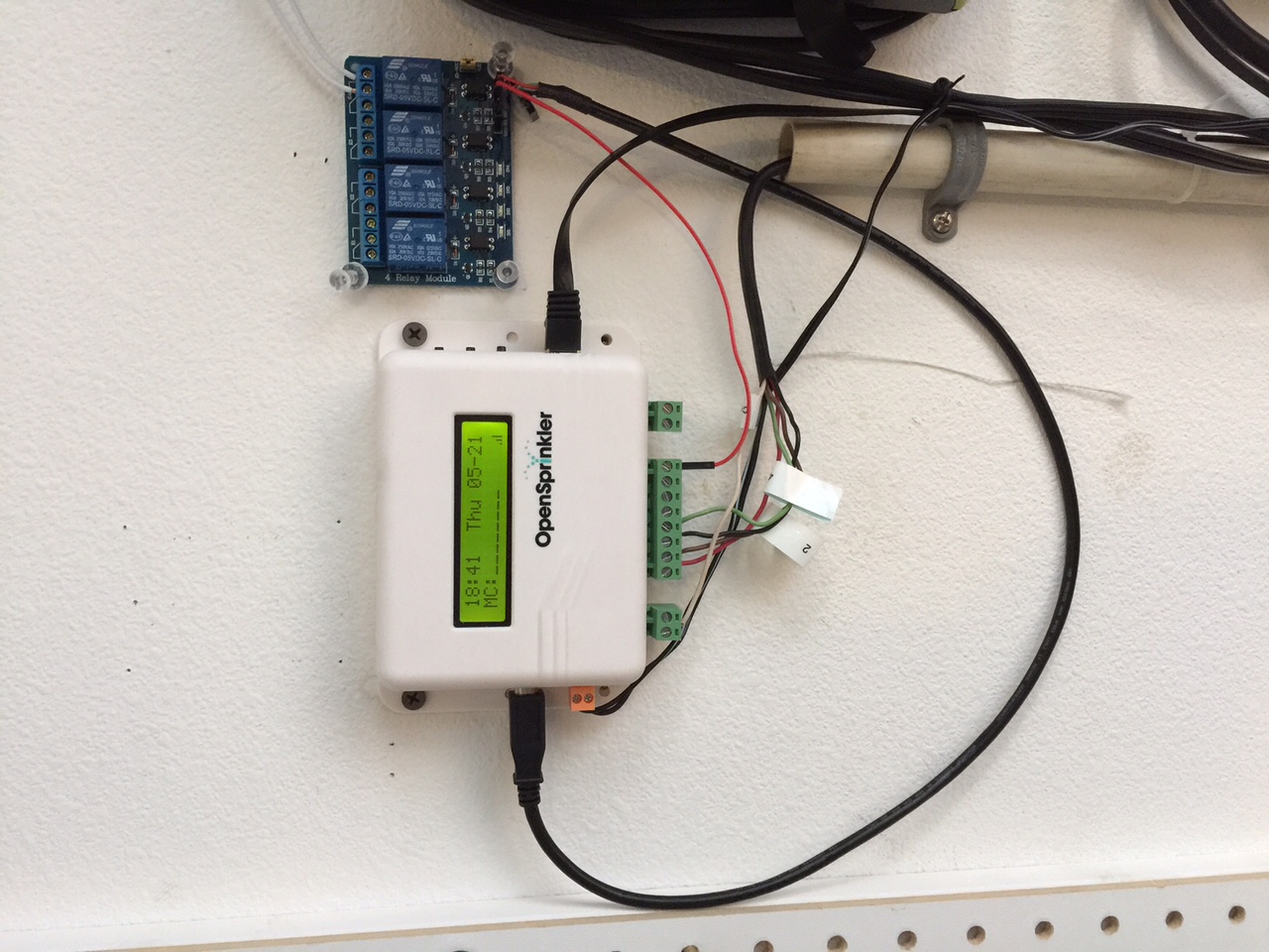
5. Attach a GPIO wire female end to one of the IN pins for which relay you want to use. In my picture I’m using #4. Attach the male end of this wire to the output of your OpenSprinkler station. I have mine on station #8.
6. Plug in the USB end of the cable to your OpenSprinkler. It’s located on the left side of the LCD.
7. Test the relay. If you manually run your station (station #8 in my example) for 1 second you should hear the relay click. If you do not check your connections or try a different relay.
8. Run your 2-wire 18 awg cable to your garage door opener. For me the opener was closer to the OpenSprinkler then the doorbell button but you can use either.
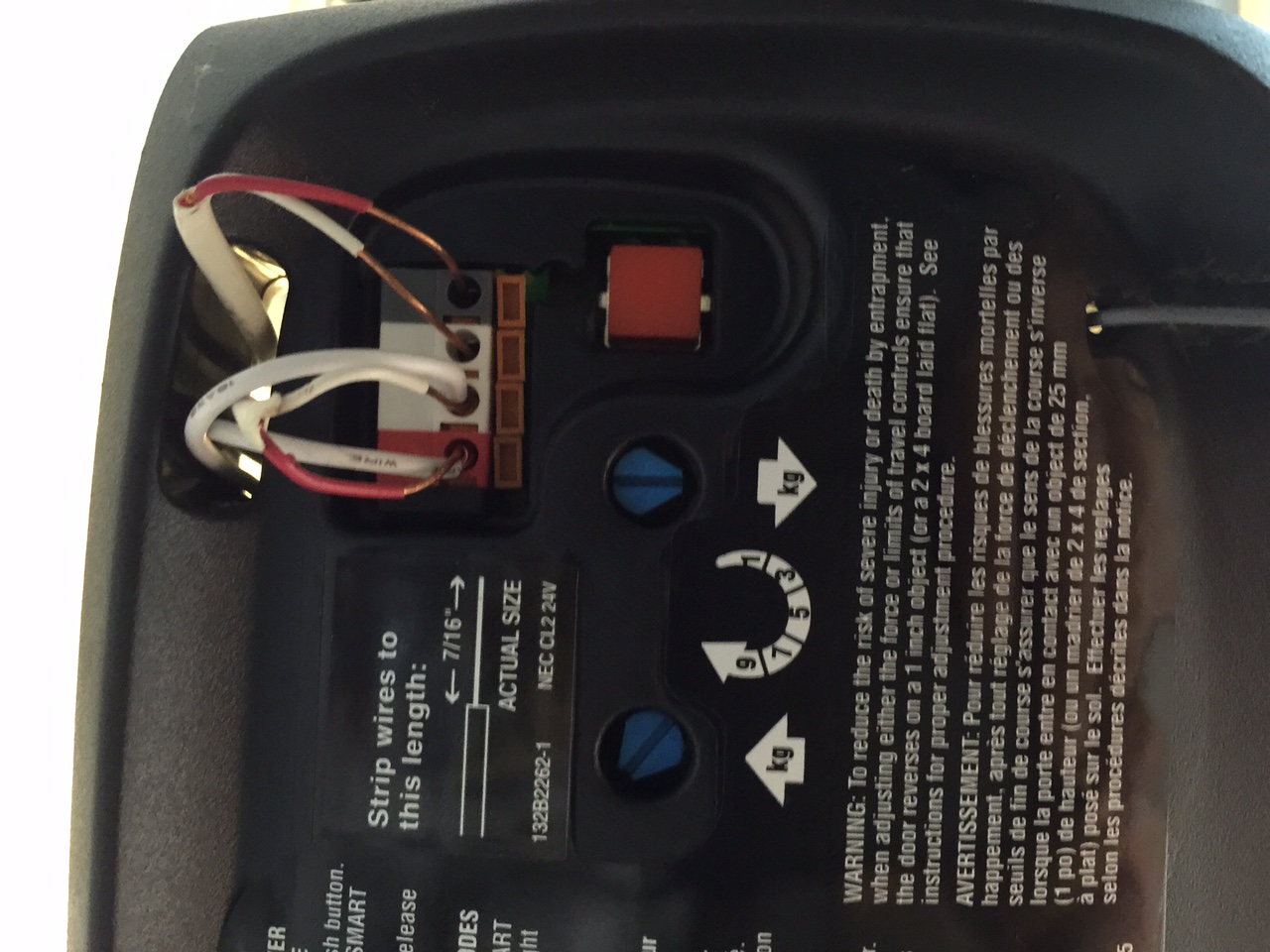
9. Determine if your garage door opener is Normally Closed (NC) or Normally Open (NO). Mine is NO which means that you need to connect the two wires to activate the garage door opener. This can be tested by pulling the doorbell/button off the wall and looking at it. It should also say in the manual of the garage door opener. Be aware though that there is voltage running through those cables so be safe.
10. Unplug your garage door opener then plug your 2-wire cable into either the same inputs on your opener or the button whichever you chose.
11. Plug the other end of the 2-wire into your relay. If your system is NO then you use the input on the right, if it’s NC then use the left (looking at the relay board with the relays on top). Either will also use the center. Just look at the wire line on the board right at the relay input and it shows you which is which.
12. Plug your garage door opener back in.
13. On the OpenSprinkler run your station for 1 second and watch it work!Attachments:
May 27, 2015 at 10:35 am #37989
RayKeymasterVery interesting. I do have some technical questions because I think there are a couple of non-trivial aspects in your approach:
1) If I understand it correctly, the relay board you are using is ‘active low’ — which means a logic LOW activates the relay and logic HIGH releases the relay. Correct me if I am wrong.
2) You can connect an OpenSprinkler’s station port directly to the relay signal pin because the station ports are essentially open-collectors (albeit driven by triacs instead of transistors or MOSFETs). This matches well with the ‘active low’ relays because when a station is turned on, that station port is connected to GND, thereby generating an active low signal which in turn triggers the relay. It’s important that OpenSprinkler and the relay board must share a common ground, which is achieved by your USB cable that provide 5V power to the relay board and the wiring ensures that they share a common ground.
3) This is the interesting part: normally triacs are not meant to work with DC voltage / current because they require a zero-crossing to properly turn off. I am guessing that it works in your case because the relay board uses opto-coupler which consumes very little current. As a result, when you turn off the zone, the DC current running through the triac is small enough that ensures the triac will turn off. This is not the case if the current flowing through the triac is larger than a few milliamps — the triac will stay on and will not turn off. That’s why triacs are really meant for AC current and not DC current. I think it happens to work in your case because the DC current is very small.
Anyways, it’s a clever approach and I didn’t think that the triacs would work with these relay boards (therefore previously I have been telling people to replace triacs with transistors or MOSFETs).
May 27, 2015 at 12:37 pm #37998
artistikoneParticipant1. From what I found documented on the board the answer is yes. LOW triggers the relay.
2. You know more than I do 🙂 I would assume you’re right since when I attempted to use an external power source (normal 5v DC cell phone charger) it failed. This lead me to using the internal USB power which was a cleaner look anyways. -
AuthorPosts

- You must be logged in to reply to this topic.
OpenSprinkler › Forums › Pictures and Creative Use › OpenSprinkler 2.1 Garage Door Opener