OpenSprinkler › Forums › Hardware Questions › OpenSprinkler Pi (OSPi) › Part lists
- This topic has 30 replies, 11 voices, and was last updated 8 years, 7 months ago by
Ray.
-
AuthorPosts
-
May 20, 2015 at 12:36 pm #37834
ArchprlestParticipantIs the part list at http://goo.gl/4Nrvb current for OSPi v1.4 +?
May 20, 2015 at 10:55 pm #37862
RayKeymasterWe don’t have a current part list for OSPi 1.4+ — first of all, you can open the schematic in EagleCAD and generate a BOM using the bom script; second, most components in 1.4+ are the same as previous versions, there hasn’t been significant change.
May 20, 2015 at 11:24 pm #37865
ArchprlestParticipantThanks
June 12, 2015 at 11:25 am #38359
ArchprlestParticipantThe PCB i was able to get was for v1.42+, I done my best to figure out the part OS the EagleCAD file i can not find. From what i can tell the only difference was the 204v 3a relay was remove for the RF connection
There is a capacitor at c7 is the a 0.1u or a 0.01u. from the pictures i can find only i can not see the C7. There looks to be different PCB for the 1.42+ opensprinkler as the comments about the VIN are different form the PCB I got.
any ways i used a 0.1u cap for C7, and I think I get the diode for D1 put in back works because when i connect power i got nothing. The fuse at f1 blow. I may have fried the buck converter also with the multi-meter props (slip when testing the voltage to see where power was not going and shorted the V in with the 5V out pin. Made some nice sparks.
I can see how the DIY kit was discontinued the SMD part are a pain to solder in place with out the right tools and very hard to get the polity right. Order some more fuses and the buck converter and will try again (hope I did not fired anything else.)
June 16, 2015 at 5:56 pm #38476
RayKeymasterOn the official version C7 is not populated. If you want you can put a 0.01uF capacitor there. It’s a filter cap and the exact value doesn’t matter very much.
D1 should be in the direction that the anode (positive) is connected to the fuse, and cathode (negative, with a strip on the component) is connected to capacitor C1.
June 19, 2015 at 2:56 pm #38545
ArchprlestParticipantGreat to hear that the value for the C7 does not really matter. I did have the D1 in backwards. after i replace the buck converter and flipped the D1 I found that the the biggest problem i had was a short on D3. now got a question; would a short (D3) that linked the 5V to ground kill the DS1307 RTC? Current i got power the the raspberry pi and the OS loaded. I can turn on each station and everything looks good, but the raspberry PI can not detect the RTC.
June 20, 2015 at 1:47 am #38554
RayKeymasterThat’s possible. Because DS1307 is powered by 5V, so any spike or overvoltage presented on 5V will damage DS1307 too. If you don’t need RTC you can just remove DS1307. It’s really only useful if there was a power break, and your controller is back online while you don’t have Internet connection. Otherwise RPi can perform NTP sync automatically to make sure it stays synced with the current time.
June 20, 2015 at 9:57 am #38561
ArchprlestParticipantthanks, i was able to pull a DS1307 from an different project, and got the RTC clock working. Last thin gi need to figure out now is with the wifi stop work after a period of time.
Thanks for taking the time to respond.
August 12, 2015 at 11:30 am #39835
fernetParticipantHi,
Can you (Archprlest) or Ray recommend a part number for the fuse at F1? Thanks.
August 12, 2015 at 8:26 pm #39850
ArchprlestParticipantI use a 2a 125vac 63vdc smd fuse from digikey. Part number 507-1080-1-ND.
August 14, 2015 at 12:48 pm #39871
sakosParticipantHi,
I would like to build the hardware on my own. I looked through the design files but some things need clarification.
– What is the exact type of TVS supressor diodes? I mean the nominal reverse voltage.
– If I do not need analog I/O can I leave out the PCF8591 A/D D/A converter chip? I am afraid if the lack of the chip causes any problem in software run.Could you plase answer the questions above?
August 15, 2015 at 1:00 am #39877
ArchprlestParticipantI am unable to answer that. I can post the parts I used. They may not be the exact part if you buy a pre-built one but it worked for me. I on holiday so won’t be able to post the list for a bit.
August 15, 2015 at 11:45 am #39879
RayKeymaster– TVS: SMBJ48CA (note that the ending is CA — bidirectional type)
– No you don’t need PCF8591 if you don’t need ADC.August 15, 2015 at 2:04 pm #39880
sakosParticipantThanks Ray,
One more question. What is the optimal lenght of the RPi support pillar (spacer)?
I have ordered the PCB from China. They produce 10 pieces on the same price as one. Is anyone interested in empty or populated 1.4+ PCB?
(I hope I do not violate any rule by asking this question here.)August 17, 2015 at 12:03 pm #39903
RayKeymasterThe support pillar is 11mm in height. We source the pillars from China. The size is M2.5×11 (i.e. 2.5mm diameter, 11mm height). The matching screws are also M2.5 screws.
August 18, 2015 at 3:12 am #39908
reinkensParticipantHi sakos,
don’t know how to send personal mail here… I’ m interested in two PCBs.
If this is possible, please reply to [email protected] for Details.Thanks,
reinkensP.S.
Thanks to Ray and all other developers. Great project!August 18, 2015 at 6:12 am #39909
DavidParticipantHi there,
i build a small PCB for the Beagle board to drive 16 relays with just two 74hct595. Its works realy good. But the board is not the best. need to improof. 😉
Now, i can controll my 220V and 12V garden lights too.
https://github.com/littleprojects/OpenSprinkler_16_relay_board
August 19, 2015 at 8:21 am #39918
akobariParticipantHi Sakos,
can you email me , about PCB board info, if you still have some? thanks [email protected]August 19, 2015 at 2:58 pm #39924
4estParticipantsakos: I am interested in the pcb. Did you received it (them)?
my email is [email protected]
August 19, 2015 at 3:10 pm #39926
sakosParticipantHi,
Some clarifications:
– I expect the PCBs arrive in 3 weeks. 🙁
– Since I ordered most of the components also, I can send the PCBs bundled with components.
– my email address is my username plus @gmx.netDecember 16, 2015 at 2:46 pm #41015
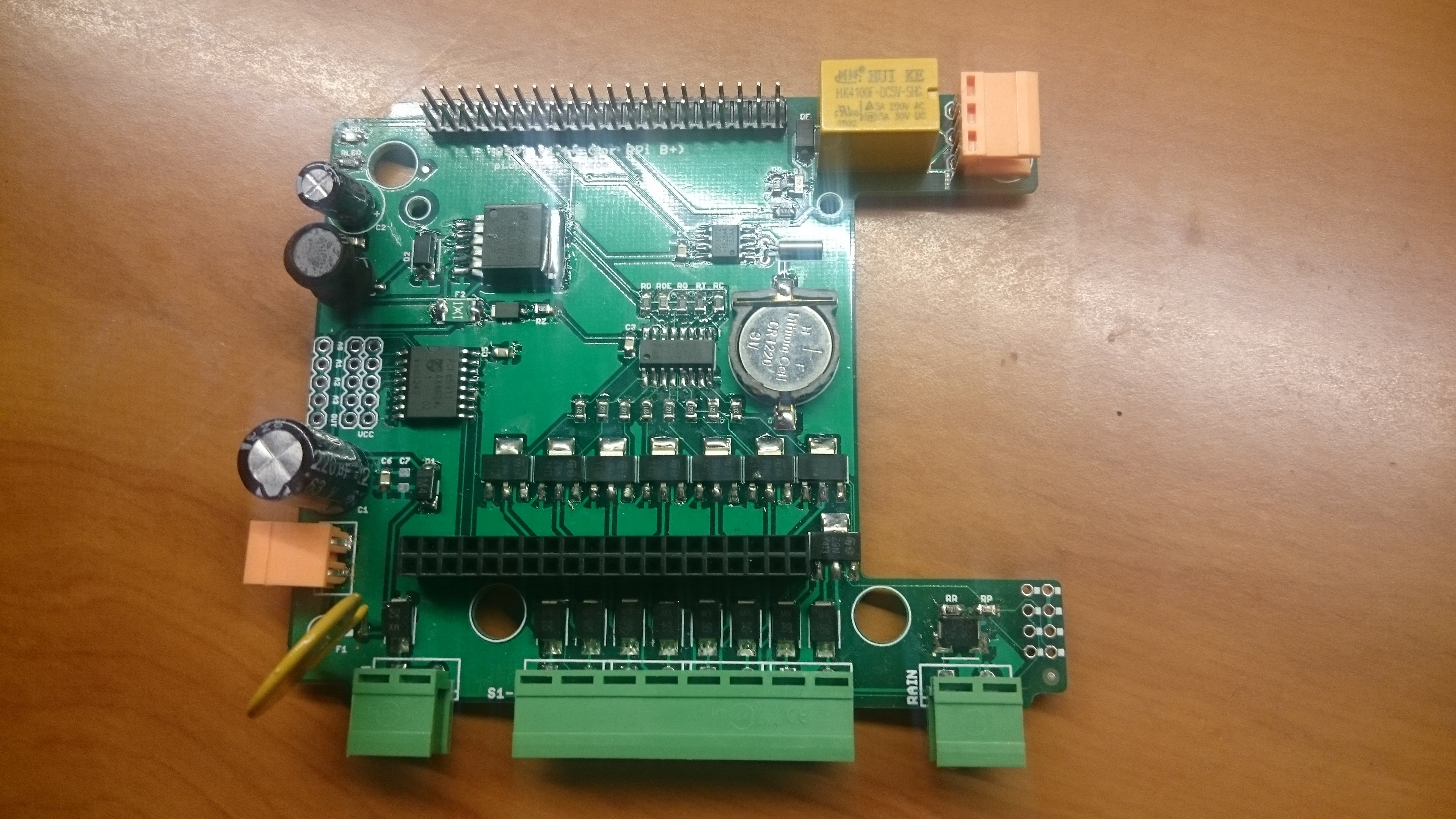
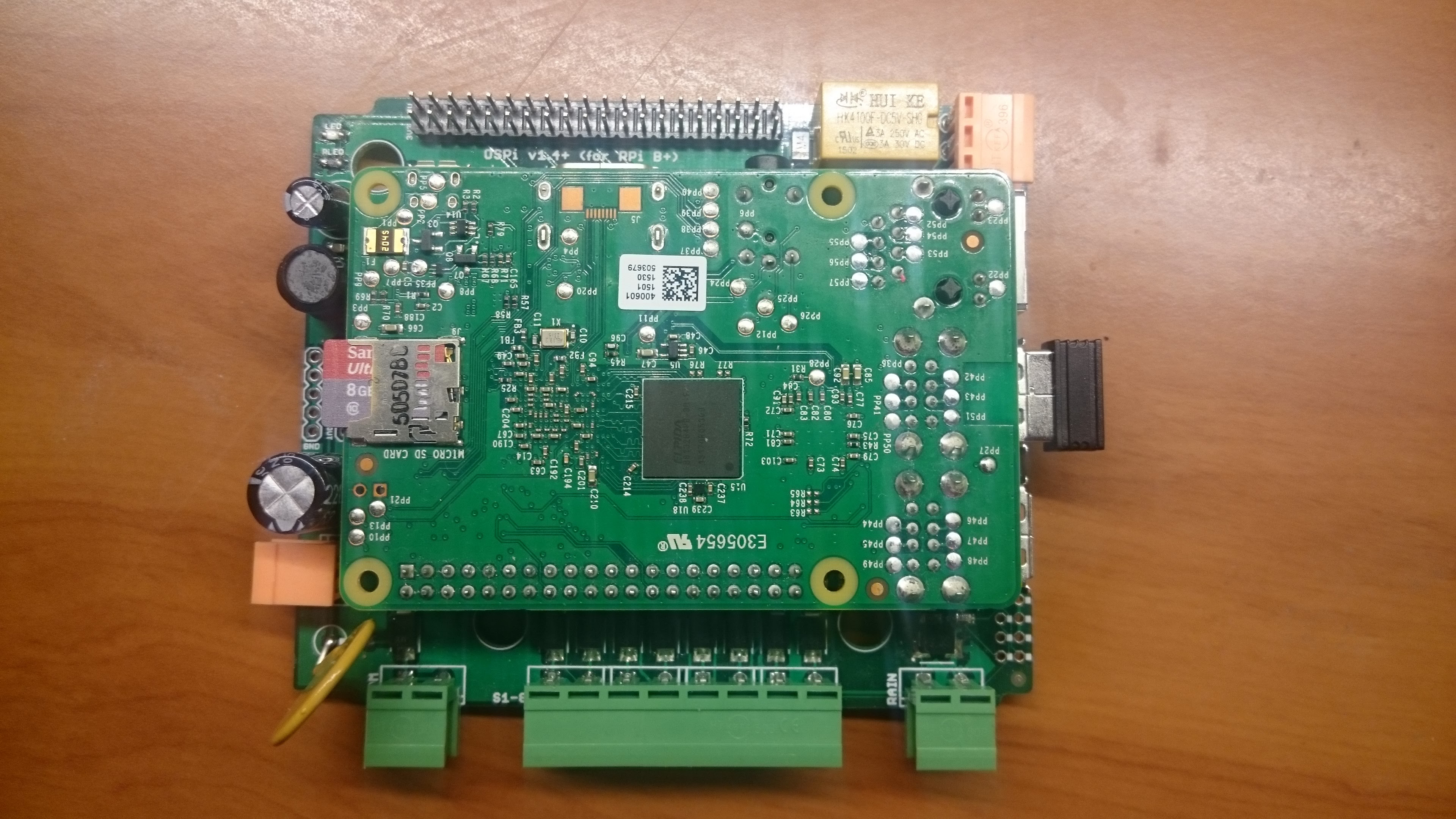
sakosParticipantI took much longer time than expected but finally I collected all components and built my own Opensprinkler PI panel. It has been tested for several weeks and working absolutely fine.
Attachments:
December 16, 2015 at 3:22 pm #41018
4estParticipantnice job!
August 8, 2016 at 12:41 am #43713
951calguyParticipantSakos I was wondering if you by any chance still have packages of components for the OSPi. Or anyone with an actual part list and info on where to get the parts please let me know. Thank you.
August 8, 2016 at 4:22 am #43715
sakosParticipantAll sold out long time ago.
The parts are available on Aliexpress online shops however it is worth buying 10 pieces of each otherwise the shipment takes the most of the cost.August 9, 2016 at 12:11 am #43724
951calguyParticipantdo you have an actual parts list? I’m trying to build the OSPi and the expansion board and when I do a BOM from eagle names, part number, and some descriptions are missing.
I’m new to the electronics area and I’m having a real hard time getting what I need.Thank you.
-
AuthorPosts
- You must be logged in to reply to this topic.
OpenSprinkler › Forums › Hardware Questions › OpenSprinkler Pi (OSPi) › Part lists