OpenSprinkler › Forums › Hardware Questions › DIY Kit Assembly Questions › Bad power supply voltages
- This topic is empty.
-
AuthorPosts
-
December 23, 2012 at 9:58 pm #22332
ChrisCraggMemberI assembled and was testing when I got a pretty bad failure. Electrolytic capacitor C2 blew. I am certain that I had the polarity right. I replaced it and retested. The measured voltage at VIN is 34.8 volts. VCC is 0 volts. Any suggestions on how to proceed?
December 24, 2012 at 6:10 am #23255
RayKeymasterFrom your voltage testing, it looks like the 24VAC -> 5V conversion and 5V -> 3.3V conversion have failed, This could be caused by any of a number of potential issues, including whether diodes D1, D2, and inductor L1 are soldered correctly, MC34063 inserted correctly, and also the 24VAC transformer outputs a voltage that’s over-spec. I suspect the MC34063 switching regulator and MCP1700-33 linear regulator are damaged. Hopefully you haven’t inserted the other ICs and the LCD — in which case MC34063 and MCP1700-33 are the only ICs you need to replace. In case you have inserted everything, I am afraid the DS1307 and the LCD are also damaged, which you need to replace as well. Do please check your 24VAC transformer output before any further experiment.
December 29, 2012 at 6:23 pm #23256
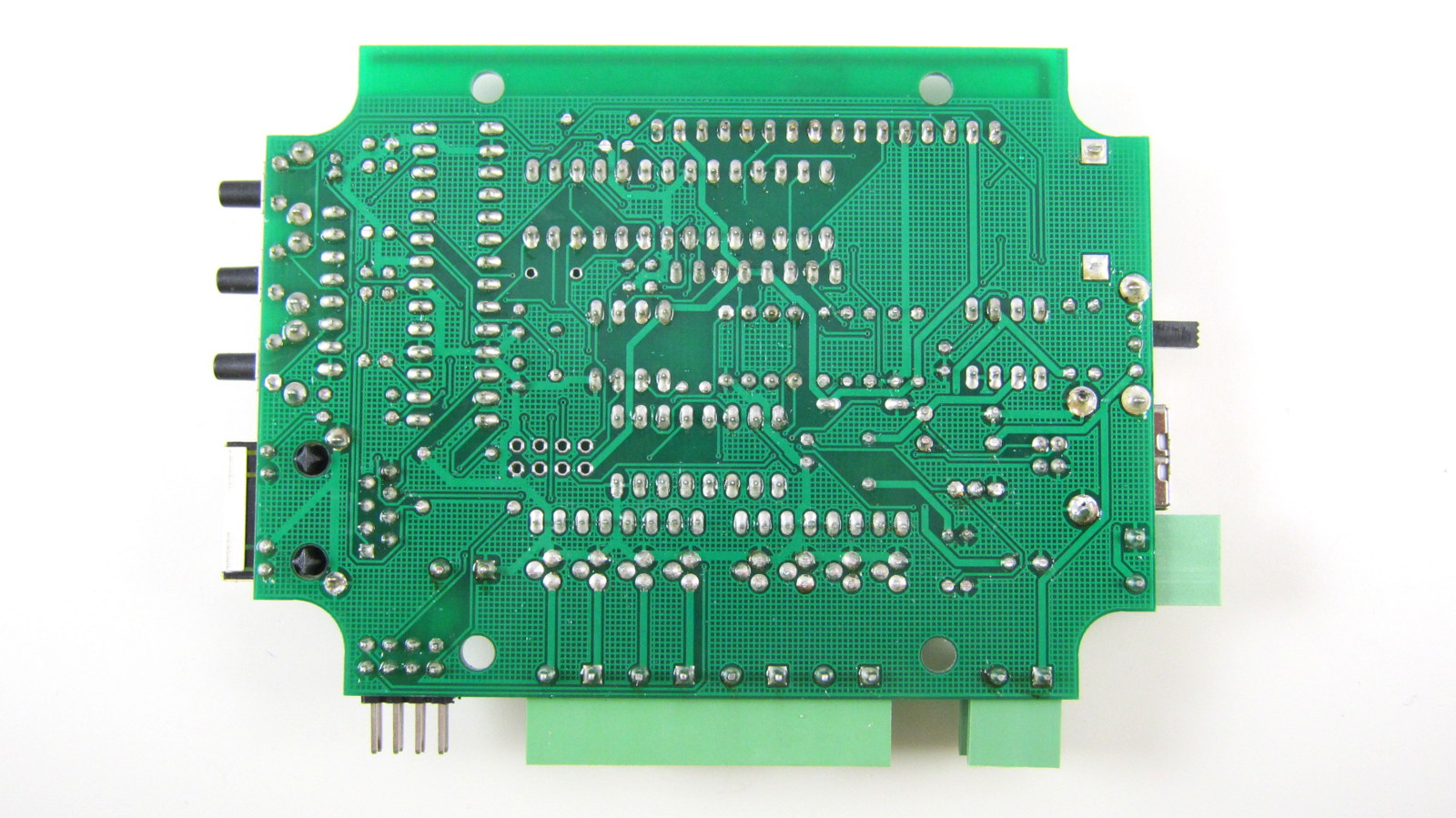
ChrisCraggMemberI have not yet figured it out. I checked for solder bridges and components not oriented correctly and don't see any problems. I've attached a picture. Do you see any problems? Are there any specific voltages I could read to help figure it out? Also, I had not installed any other components, so the only things at risk are what is on the board.December 29, 2012 at 6:52 pm #23257
RayKeymaster1. The front looks ok. Could you also post an image of the back of the PCB so I can see the solder joints?
2. Could you use a multimeter to check the AC (not DC) voltage of your sprinkler transformer? What’s the reading?January 16, 2013 at 10:53 pm #23258
ChrisCraggMemberScan of schematic with voltages annotated on it attached.
January 16, 2013 at 11:20 pm #23259
RayKeymasterLooks like both the MC34063 switching regulator and MCP1700 linear regulator are damaged. Not sure why that happened. I do have some spare parts I can send you. It will be on the way tomorrow. This will include the two regulators, inductor, and two diodes (R3000 and 1N5819). My suspicion is that you probably only need to replace the two regulators. For diodes, use your multimeter to check the forward drop voltage: R3000 should be around 1.5V to 2V, and 1N5819 should be around 0.2V. If not, replace the diodes as well.
Be careful desoldering components off PCB: probably the safe way is to clip the leads off the component body first, then you can desolder each lead one by one, or in some cases directly solder a new component on the leftovers of old leads. Do not use too much strength to pull out leads, or you may damage the PCB trace.
April 25, 2013 at 9:14 pm #23260
riveranlMemberDear Ray,
I am having the same problem and you should have recived an email from [email protected] concerning our problem. We would like to know if we could get just the prebuilt and pretested board. We will not need the terminal blocks, LCD Screen or case. Please respond to [email protected] or [email protected].Thank You!! 😀
April 25, 2013 at 9:46 pm #23261
RayKeymasterAlready replied to you.
May 5, 2013 at 5:17 am #23262
Rich_HMemberHi everyone,
Got to the “hook up the power” test. I’m using a Rainbird 26VAC, 700ma transformer off my existing irrigation controller. AC output measured 27.2VAC on a Fluke 8080 multimeter when the transformer was plugged into the power strip on my bench without a load.
After installing the battery, I installed two leads into Power In connector, turned on the power switch and immediately smoked IC1, the MC34063. 😮
There was a pop and smoke, the epoxy case is cracked between pins one and two on the MC34063. 🙁 IC1 is definitely toast…
Nothing else (IC or LCD) was installed per instructions. The IC1 was oriented properly, all the pins were seated in the chip holder. I’ve been going over the board as I build it with a magnifying headset looking for cold solder joint, solder bridges, etc.
Can you tell me where to measure voltages around the PCB without MC34036 installed to confirm operations and most importantly, where is a good ground for all my measurements?
BTW, the instructions are missing a step to install the rain sensor contacts (they are in the photo but missing in the instructions). Also, I was shipped three 220 uf electrolytics instead of 2 x 220uf and 1 x 10uf so whoever is picking your parts is messing up. I was able to get the 10 uf electrolytic locally so installed it & don’t need a replacement….
Regards,
rich
May 6, 2013 at 4:18 am #23263
RayKeymasterIt’s difficult to pinpoint the exact reason without seeing your board and soldering quality. Here is a reference image of the soldered board:
http://rayshobby.net/wordpress/wp-content/uploads/2013/04/svc142_build_back.jpgThere are a few tests you can start with:
– measure the resistance between VIN and GND, and also VCC and GND. If any of them is small (less than kilo-ohm level), there is probably a short somewhere.
– since your IC1 is burned, you should also check the related elements, particularly D1, D2, D3, and see if they have been damaged in any way. To check these diodes, use a multimeter to measure the forward drop voltage. D1 and D3 should have 0.5-0.7V, and D2 should have around 0.2V. If the forward drop voltage is shown to be close to 0, the diode is burned and needs to be replaced.
– Try to power the circuit board through USB and measure the voltage between VIN and GND, and also VCC and GND, see if they are roughly 5V and 3.3V respectively.Regarding the three 220uF capacitors, I apologize for the issue. Just to make sure: since the 220uF and 10uF capacitors are very similar in appearance, did you check the label on the capacitor body to see they are actually all 220uF?
Thanks for pointing out the missing Rain Sensor step. Will add that to the instructions later.
May 14, 2013 at 2:53 am #23264
mrburns42MemberI suspect that the problem is with the switching diode D2. Either this diode is defective, the wrong part, or perhaps it is interchanged with D1. D1 is a garden variety rectifier. D2 needs to be a schottky fast recovery diode. A regular diode at location D2 will not clamp the inductive kick of L1 fast enough and allow a negative voltage to be applied to both IC1 and C2. This would explain while those two parts are failing.
My suggestion is to replace IC1, D2 and C2 with known good parts. Verify the markings on D2 versus the datasheet and make sure it is oriented in the circuit correctly. From the picture, I think I see an “R” on that component. Since “R” is not part of the IN5819 part number, this must be part of some manufacturer’s number. Once these three components are populated with known good parts, then I would have all other IC removed and attempt to power the board from a 9V battery. I think one nine volt battery should be enough to run IC1 with no load. See if you get something close to a five volt output and that IC1 runs cool. If IC1 is hot and the input rail is dragging down the nine volt battery, then something else is loading the circuit.
-
AuthorPosts
- You must be logged in to reply to this topic.
OpenSprinkler › Forums › Hardware Questions › DIY Kit Assembly Questions › Bad power supply voltages