OpenSprinkler › Forums › Comments, Suggestions, Requests › GPIO Stations
- This topic has 15 replies, 6 voices, and was last updated 9 years, 1 month ago by
Peter.
-
AuthorPosts
-
January 10, 2016 at 11:32 am #41241
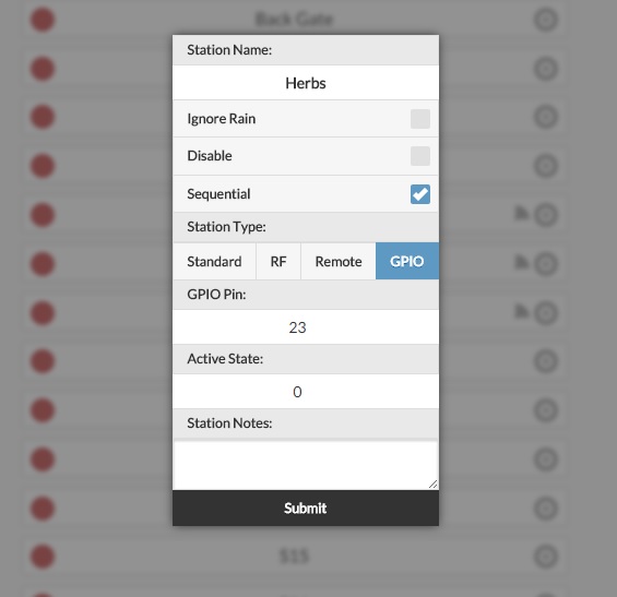
PeterParticipantOver the weekend, I needed to add two more zones to an already full OSPi. I had a few relay circuits to hand and since the OSPi has a number of free GPIO pins, I connected them up and modified the Special Station functionality that supports RF and IP stations to also control a raw GPIO pin (see UI attached). In essence this allows you to bypass the shift register/triac/protection circuitry of the OSPi and control directly a spare RPi gpio pin and any connected homebrew relay hardware.
It took me awhile to get my head around the Remote Station paradigm as OSPi uses a “send and refresh” approach i.e. if you programme an Remote Station station for 30 minutes then OSPi will send a 5 minute water command every 2 minutes until the end of the programme when a stop command is sent. This makes sense for RF and IP stations where messages may go missing and you want to fail safe. This seems to work fine in the case of a GPIO Station as well in that the added code sets the gpio high and then every few minutes just re-affirms the pin high before setting it low at the end of the programme. The approach looked to be the least intrusive way of adding this functionality – you can use the UI to associate any gpio pin with a station and set whether the hardware is active high or low. There are only about 20 lines of modification across Firmware and App.
The result seems to have worked well in watering my new herb and veg garden! Curious if anyone sees a problem with the approach – putting safe hardware design to one side and avoiding gpio pin conflicts – and if other would find useful?
Attachments:
January 11, 2016 at 2:18 pm #41265
RayKeymasterGreat! Thanks for sharing. This is a nice extension, and glad to hear you were able to modify both the firmware and UI to achieve the feature. We should probably integrate this into the code. Regarding safety, to begin with, the UI can check to allow only available pins (i.e. those that have already been assigned to other functions are not available), and the firmware can do its own independent checking to double check.
Regarding the ‘send and refresh’ approach for remote stations — I know it sounds intuitive, but the main reason to do it this way is that currently the remote stations are one-way communication — the master controller does not check the return from remote controllers to ensure the station is on/off as it’s supposed to. So to make sure the remote station is in sync with what master controller thinks it’s doing, the ‘send and refresh’ is used. Actually even for the standard stations (connected through the shift register), there is a 1-second refresh to ensure it’s in sync — otherwise if there is any signal interference that could leave the station on unintentionally.
January 16, 2016 at 9:11 pm #41314
PeterParticipant@Ray/Samer, I have done a pull request on both Firmware and App. Appreciate any feedback via github. Peter
January 19, 2016 at 9:38 pm #41348
RayKeymasterCool. Thanks. I will take a look and approve as soon as possible.
February 14, 2016 at 2:12 pm #41513
PeterParticipant@Ray/ @Samer, thanks to you both for integrating this into the master branch. I couldn’t find the api and user manual on github so have included below the documentation changes to reflect the GPIO Station functionality. happy to make the changes if you point me at the source documents. Cheers, Pete
1) OpenSprinkler Firmware 2.1.6 API Document – Add following bullet in section 8 Get Special Station Data
• (OSPi only) st=3: gpio station. sd stores the gpio number and active state for the attached relay in the following order: gpio number in zero-padded, ascii format (2 bytes) and active state as either ascii “0” or “1” (1 byte) e.g. sd = “051” for an active high relay attached to GPIO5.
2) OpenSprinkler v2.x User Manual – Replace the word “two” with “three” special station types
Station Type: the default type is Standard. Beyond that,
twothree types of special/virtual stations are supported:3) OpenSprinkler v2.x User Manual – Add following to Section 3.2 Station Attributes/Station Type
• GPIO station: (OSPi only), A GPIO Station allows you to connect your own switching hardware to one of the many Raspberry Pi GPIO pins available on the OSPi motherboard. This allows you to extend the number and type of stations you can control from an OpenSprinkler main controller. GPIO Stations simply send “on” and “off” signals to the selected GPIO pin and rely on the connected hardware to physically switch the downstream station. A GPIO Station is specified by a GPIO pin number and whether your hardware is active HIGH or LOW i.e. requires a +3.3V or 0V signal to switch on.
4) OpenSprinkler v2.x User Manual – Substitute picture on Section 3.2 Station Attributes
Replace image with one attached
Attachments:
February 17, 2016 at 12:43 am #41547
RayKeymasterThanks Peter, for summarizing the changes. I will integrate these changes to the user manual asap.
March 11, 2016 at 4:57 am #41714
loop_1ParticipantPeter, so with your mod i can use a relay board connected to my Raspy, it is correct?
March 11, 2016 at 9:11 am #41716
PeterParticipantThat’s correct. I am really glad Ray and Samer agreed to include the GPIO Station stuff as that along with the Remote Station functionality makes the ecosystem very extensible and opens up new control scenarios. I have three setups at home:
1) Main Controller in the back garden: I wanted to add two more stations to my main back garden OSPi controller that already had 8 valves and a flow meter connected. I did this by wiring up a sainsmart dual-relay board that I had lying around to a couple of free gpio pins. I use the GPIO Station functionality to get OS Firmware to control the extra relays and connected valves.
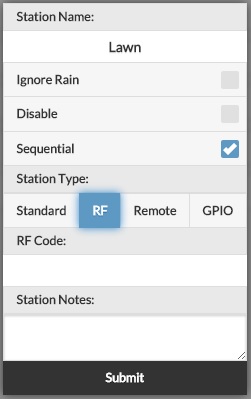
2) Remote Station in the front garden: I live in a terrace block and needed a way to irrigate a small front lawn but can’t run a cable to the main OSPi controller in the back garden. So I wired up a single mechanical relay to a RPi Zero and run OS Firmware with GPIO Station functionality to control a single valve. The RPiZ has wifi usb to connect to my network and is setup as a Remote Station on the main OSPI controller in the back garden so that I can keep all of my programme scheduling centralised.
3) Indoor Station: I wanted to control my Claber Oasis indoor watering system in the same way as my front and back garden setups so I have combined an ESP8266 with a motor shield to drive the 9V DC latching valve on the Claber. I have custom code running on the ESP that mimics the OpenSprinkler Remote Station api so that the main OSPi controller in the back garden can turn the Claber valve on/off using the Remote Station functionality. Again, keeps all the programme scheduling together.
Cheers, Pete
April 21, 2016 at 1:06 am #42152
cyberumbParticipantHow can I add GPIO Station functionality mod to current OpenSprinkler App?
Thanks,
April 21, 2016 at 8:47 am #42160
SamerKeymasterI will be updating the app store applications very soon with this support added. Thank you for your patience.
May 18, 2017 at 7:19 am #46288
crossmaxParticipant3) Indoor Station: I wanted to control my Claber Oasis indoor watering system in the same way as my front and back garden setups so I have combined an ESP8266 with a motor shield to drive the 9V DC latching valve on the Claber. I have custom code running on the ESP that mimics the OpenSprinkler Remote Station api so that the main OSPi controller in the back garden can turn the Claber valve on/off using the Remote Station functionality. Again, keeps all the programme scheduling together.
Hi @Peter, I have contacted you from another thread where you related that you had managed to operate a latching valve with L293D H driver.
I’m very interested to know how has managed to make compatible OS software with this type of valves. I think the only way to do it is to assign two gpio pins to each station, one pin to indicate to the driver +9V and another pin to indicate -9V.
BTW, I haven’t been able to make this change in the source code.Can you tell me how I can do it?
P.D: I’ve tried contact you via private message or via github but there are no such options.
Thanks
May 18, 2017 at 3:07 pm #46292
PeterParticipant@crossmax, I think what you are looking to do is use a single raspberry pi to run the OSPi firmware and to also control a latching solenoid? This is different to my situation. I do not have OS firmware controlling GPIO pins to drive latching valves. The firmware is not geared up to do this out-of-the-box as you mention above.
In my case. I already had an OSPi controller running all of my stations, programs and regular valves out in the garden. My goal was to find a way to add an indoor latching value into the system without having to run wires into the house. So I wrote a bespoke program to run on an ESP8266 that simply “listens” for on/off commands from the garden OSPi and in response opens/closes the latching valve. So my solution has OS firmware running on the garden RaspPi and a simple gpio routine running on the ESP not a combined unit.
You can check out the this post where I set out the solution. I’m happy to post the code if useful and talk through the hardware but it was Arduino based for an ESP8266. So it would not be a simple copy and paste onto a Raspberry Pi.
If you really want everything in the one unit then I think you would need to either extend the OS firmware to support latching valves or alternatively create a “man-in-the-middle” programme that monitors the OS firmware status and then appropriately configure the H-Bridge hardware. You should also check out the new OSBee 2.0 unit as an option
Happy to talk through.
PeteMay 19, 2017 at 8:57 am #46298
crossmaxParticipant@Peter, Thanks for your answer because it has opened another possibility that I had not contemplated.
My fisrt idea was try to do a wireless system with 9V baterry for control valve. I posted this thread where I explain it. I think it is impossible to do without adding a solar panel and I find it easier to have a power supply.As I have a ESP8266MOD in my jumble case. Can you share your arduino code? I think it is compatible with my ESP. Time ago I fashing it with Arduino IDE. I’ll be very grateful to you.
Thanks again.
P.D: Maybe it would be better to continue this conversation in your post about indoor watering systemMay 22, 2017 at 11:04 am #46382
PeterParticipant@crossmax, No problem. I have put up the code I’m using on my GitHub here. It is specific to the Motor Shield that I have but should be pretty easy to modify depending on the particular hardware configuration you are using. Happy to help out so feel free to follow-up in the other thread or via github. Cheers.
May 23, 2017 at 7:22 am #46395
crossmaxParticipant@peter
Thanks for share it!
I’m trying to flash but i get compilation errors. I’ve to install Time library from this link but seems is not compatible with your code.
I not have yet installed arduino library (#include <arduino.h> not found returned).Would you be so kind to link the libraries you have used? I’m newby to arduino
May 23, 2017 at 12:19 pm #46403
PeterParticipant -
AuthorPosts
- You must be logged in to reply to this topic.
OpenSprinkler › Forums › Comments, Suggestions, Requests › GPIO Stations