OpenSprinkler › Forums › Hardware Questions › OpenSprinkler Pi (OSPi) › How do I connect the RF transmitter?
- This topic has 28 replies, 3 voices, and was last updated 9 years, 1 month ago by
Ray.
-
AuthorPosts
-
April 17, 2015 at 8:49 pm #36829
SeanParticipantI have a new OSPi, H/W version 1.4.
I have followed the video to integrate the RF transmitter to the OSPi and all has gone well until I attempted the final step of soldering the transmitter to the board.
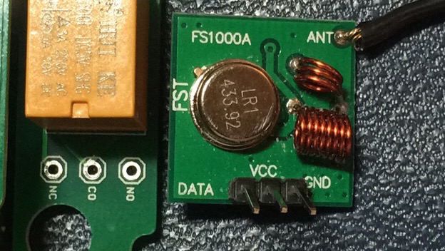
The version of board I have does not have three through holes in a group labeled A3, VIN and GND as the instructional video shows (see RaysVideo.png). The only group of three holes I can find are labeled NC, CO and NO (see IMG_0758.jpg)are these the right ones? If so, what is the translation?
I did see a set of 15 holes, (see IMG_0760). it looks like an entire row of five are labeled VCC, one of the holes in an adjoining row is labeled A3 and another entire row is possibly labeled GND. Do I use these?
Is the RF Transmitter even compatible with the OSPi?
Help?
Sean
P.S> sorry for the duplicate picture attachments. My first attempt posted in the revers order of how I put them. When I tried to edit the attachment list I ended up double posting them because attachments are not available in the “edit post” screen.
Attachments:
April 18, 2015 at 9:40 am #36842
RayKeymasterWhat you have is a microcontorller-based OpenSprinkler (looks like it’ a DIY kit), it’s not OSPi. So this is actually not the right subforum for this post.
The A3, VIN and GND are the three pins to connect to RF transmitter (they correspond to DATA, VCC and GND). I apologize that the user manual is only showing an exmaple for the fully assembled OpenSprinkler, while yours is a DIY kit. But yes, A3, VIN and GND are the three pins you are looking for.
April 18, 2015 at 10:39 am #36843
SeanParticipantNo. I have an OSPi Plus version.
Attached pictures with file names starting with “IMG_” are pictures I took of the OSPi + board that I have.
This is the correct subform and I still need help.
April 18, 2015 at 7:48 pm #36865
SeanParticipantMy OSPi is still in pieces on the kitchen table waiting for an answer to my original question.
If anyone here has successfully connected an RF transmitter to an OSPi Plus, could you speak up and tell me how the connection is made?
April 19, 2015 at 10:00 am #36886
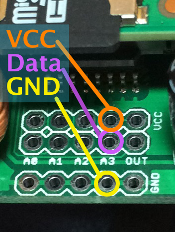
SeanParticipantAssuming that A3 is the same on the microcontorller-based OpenSprinkler and the OSPi board, I am going to connect the RF transmitter to my OSPi per the attached image and hope that it doesn’t fry something when I apply power.
Attachments:
April 19, 2015 at 11:17 am #36892
RayKeymasterHi Sean, sorry for my confusion, now I understand, yes, you have OSPi (I was judging from the picture you posted that you have an OSDIY).
So, I have to clarify to you that only recent OSPi Plus boards (version number 1.42) have added the pin headers for RF transmitter. What you have is probably the original version which comes with a yellow relay and not RF transmitter headers. Since a couple months ago, we’ve decided to retire the relay, but instead add RF pin headers.
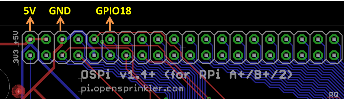
The firmware by default uses the same pin (originally assigned to relay) for the RF transmitter. So I think the easiest way is probably to pick a different GPIO pin (GPIO18 is recommended), and modify the firmware to match your new pin. Check the attached image for suggested pins. Basically you can connect RF transmitter’s DAT, VCC, GND pins to GPIO18, +5V, GND pins marked in the image. (although the transmitter can work with 3.3V, use 5V helps boost its transmission range). Next, modify the PIN_RF_DATA defined in defines.h (under the #if defined(OSPI) section) to 18 (originally it’s 15, which is the same as the relay pin). Then recompile the firmware. This should allow you to use RF transmitter. Let me know if this is clear.
Attachments:
April 19, 2015 at 1:25 pm #36897
SeanParticipantI’ll try that, thanks.
Befor I do, could you clarify something?
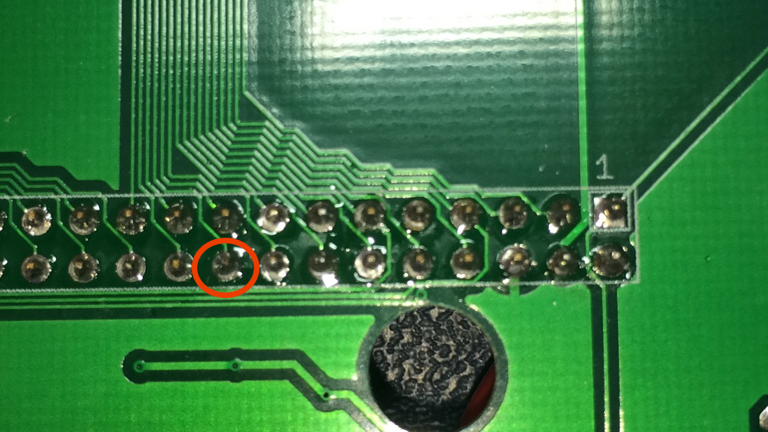
I did a quick continuity check based on your illustration and found that my GPIO pin 18 does not seem to match the illustration you provided. I could easily have counted the pins wrong though.
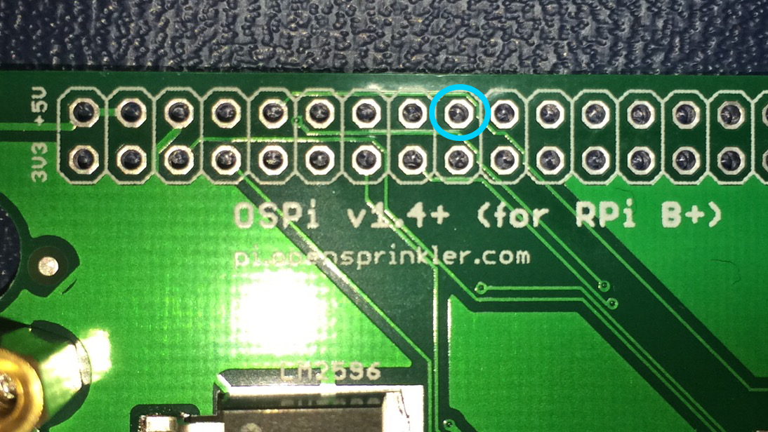
On the reverse side of the board, is the pin I have circled in red in Pic1.png actually GPIO pin 18?
If so…
On my board, that pin has continuity to the contact that I have circled in blue in Pic2.png.
Did I get this wrong?
April 19, 2015 at 4:00 pm #36902
SeanParticipantNever mind.
I confused myself. I assumed that GPIO18 would be on pin 18 of the GPIO connector.
I just looked at the Raspberry Pi v2 pinout and learned that GPIO18 is actually on pin 12, not pin 18.
Last question, Will I need to modify and recompile each time a new version of firmware comes out?
April 19, 2015 at 7:16 pm #36907
SeanParticipantWell I made the change to defines.h (see attached) and recompiled. I connected the transmitter properly (I think).
I captured and tested the transmitter codes. They work if transmitted by the RFToy.
I configured the station names to match the transmitter codes (see attached).
Still, it does not work.
My first assumption is that I crossed wires connecting eh transmitter. I will check that. while I do, Can you teak me if I have the right firmware? Is there something else I should check?
App Version: 1.4.1
Hardware version OSPi 1.4
Firmware Version 2.1.3.Attachments:
April 20, 2015 at 12:36 pm #36935
RayKeymasterHi Sean, to diagnose the issue, the easiest way is to use the RFToy to listen to your OSPi when it sends the signal, and see if it can decode the signal. If nothing is detected at all, it might be a wiring issue. If it detects the code, but the last four digits (which record the signal timing) is very different, that’s most likely due to a timing calibration issue, and that’s easy to fix by tweaking the last four digits.
April 20, 2015 at 9:15 pm #36969
SeanParticipantBrilliant idea!
I’ll try it tonight.
April 20, 2015 at 9:43 pm #36970
SeanParticipantNo signal. So, I will dig out my kit and find out where I went wrong.
Thanks again.
April 21, 2015 at 8:20 am #36977
RayKeymasterA useful tip is that if you have a cheap computer speaker you can place it close to the transmitter — when it transmits, the speak often picks up the signal and you can hear some sort of beeping sound. Probably not all speakers will pick up the signals, so try your remote control first and see if the speaker can pick it up. Then try OSPi. If there is no actual signal sent out from OSPi, you should check if +5V and GND are wired to the transmitter correctly. Also, after you modified the source code, and recompiled, you should restart RPi to effect the changes.
The computer speaker trick can also allow you to identify if the simulated signal roughly matches the original signal. Specifically, the pitch you hear is correlated with the signal timing — the slower the signal, the lower pitch you will hear.
April 21, 2015 at 10:07 pm #36997
SeanParticipantConnections are good.
4.92 VDC to GND at the transmitter, not polarity reversed.
No signal detected by the RFToy.
Have not tried the speaker trick.
The time stamp of the opensprinkler file agrees with when I compiled it.
Still no workie
I wonder if I fried the transmitter. I’ll try it in the RFtoy tomorrow.
Other than that one change in defines.h, was there anything else in the 2.1.3 code that deeded changing?
April 22, 2015 at 10:29 am #37006
RayKeymasterI don’t think there is anything else you need to change.
As a sanity check: you can change the pin definition back to 15, recompile and run the firmware. When it sends a signal, you should hear the relay making a noise. If not, I suspect the 16-digit HEX code you entered is not right — the firmware will detect if it’s a valid code, so if it’s not exactly 16-digit long, or if any character is not a hex code, it will not recognize it as a valid RF code.
April 26, 2015 at 9:41 pm #37134
SeanParticipantOK, I changed the pin definition back to 15. There is noise from the relay.
The names are 16 digit hex. Here are the names:
“51153351153C00C0″,”5115C35115CC00C0″,”51170351170C00C0″,”511D03511D0C00C0″,”51350351350C00C0”
The unit has an extension module that was not connected during this test.
The RF stations are numbers 41 through 45.
The next thing I am going to try is defining one of the first 8 zones as a transmitter.
April 26, 2015 at 10:14 pm #37136
SeanParticipantNo joy.
changed the rf data pin definition back to 18 and recompiled. The rftoy picks up no signal.
I wonder if I fried the transmitter when I connected it to the OSPI?
The next thing I’ll try is removing the extension wires from the transmitter, cleaning off the pins and plugging it back into the rftoy to see if it still turns on the rf outlets.
April 27, 2015 at 9:54 pm #37155
SeanParticipantreconnected the transmitter to the RFToy and verified that it works.
So, it looks like there is an issue with my OSPi.
Hardware:
OSPi controller version 1.4
Two extension modules
Raspberry Pi 2 model B
Two Netgear Powerline 500 ethernet adaptersSoftware:
Noobs version 1.4.0
OSPi firmware version 2.1.3April 27, 2015 at 11:20 pm #37175
RayKeymasterSeems like perhaps the pin number 18 isn’t correct — in other words, it’s not matching the actual pin you are using. Clearly the firmware is able to send the signal out to pin 15. Maybe you should double check the wiring, and double check the GPIO number — this is the only possible issue I can think of.
In the worst case, you can probably just use GPIO 15 (the pin that’s connected to relay). The relay will make a noise, but the RF transmitter should still work along with it.
April 28, 2015 at 7:18 am #37182
SeanParticipantTwo things:
1) Are there GPIO pins you are not using other than 18? If it is not in the section that you pointed me to in the defines.h file can i assume that I can try the transmitter data there?
2) There seems to have bee several changes to the P1 pinout for the new Raspberry Pi 2. There is a discussion HERE and a detailed explanation HERE. This is over my head, so I hope you can make sense of it. Could these be related to my issue?
April 29, 2015 at 10:09 pm #37227
RayKeymaster1) The pin 18 which I suggested is just a suggestion — it’s the GPIO that’s next to pin 15 is not being used. But you can use any GPIO pin that’s not currently used by OSPi.
2) I hate to say this but RPi makes a lot of changes and it’s a bit hard to keep up with.
As I said, since pin 15 works (e.g. you can hear the relay noise), why not just use that pin. The fact that relay is connected to that pin shouldn’t matter with the transmitter. You can always desolder the relay if you can (although it’s a bit tricky since a relay has 6 pins).
April 30, 2015 at 1:18 pm #37259
SeanParticipantI’ll try GPIO15. Then de-soulder the relay if it works.
In the meantime, can you post all the GPIO that are unused?
April 30, 2015 at 7:24 pm #37270
RayKeymasterYou can check that information from the OSPi user manual:
http://rayshobby.net/docs/ospi14_manual.pdf
page 10.May 1, 2015 at 9:00 pm #37292
SeanParticipantRay thanks for your help. But…
I’m done
I moved the transmitter data to GPIO15 and recompiled/rebooted. Nothing but relay noise. The transmitter is not being fed a signal that it can use.
I tried a get pull and rebuild/reboot. Same. Nada.
The only conclusion I can come to is that OSPi 1.4 with Raspberry Pi2 using either 2.1.3 or 2.1.4 does not drive the RF transmitted from your store.
May 4, 2015 at 12:06 am #37333
RayKeymasterI’m confused: I thought you said the transmitter worked with the RFtoy, which means the transmitter itself is working, is that right?
-
AuthorPosts


- You must be logged in to reply to this topic.
OpenSprinkler › Forums › Hardware Questions › OpenSprinkler Pi (OSPi) › How do I connect the RF transmitter?