OpenSprinkler › Forums › Hardware Questions › OpenSprinkler Pi (OSPi) › OSPi Ver 1.3 layout request
- This topic has 16 replies, 2 voices, and was last updated 10 years, 10 months ago by
Ray.
-
AuthorPosts
-
October 13, 2014 at 10:58 pm #33871
4worldParticipantI have searched hard on the forums as well as on Google but couldn’t find the PCB layout (silk screen showing Ref. designators) for Open Sprinkler Pi Ver. 1.3
It’s needed URGENTLY so I would appreciate if someone please points me to the archives or where it can be found.
Thanks.
October 13, 2014 at 11:48 pm #33876
RayKeymasterIt’s in the OpenSprinkler Github repository: https://github.com/rayshobby/opensprinkler/tree/master/OpenSprinkler%20Pi/hardware
October 14, 2014 at 9:35 am #33890
4worldParticipantHi Ray and thank you for such a super prompt response.
I had already checked that place. There are only 3 files related to Ver 1.3 there – a SCH, PNG and BRD. I cannot open the SCH or the BRD files since they are probably source files of OrCAD/Cadence or some other similar schematic and board layout program — I needed a PNG/JPG to view the silk screen layout just like you provided the PNG for the schematic.
Thank you for your help.
October 14, 2014 at 12:18 pm #33899
RayKeymasterPLEASE, check the readme.txt in the repository:
Note: requires Eagle CAD v6.0 or aboveJuly 28, 2015 at 11:50 am #39536
4worldParticipantHi Ray,
Please see the above old thread. I don’t have any CAD software and just need: a) The silk screen and b) The traces (both sides) layout.
Other older versions of the above have PNG and/or JPG files on your repository but not this one (v1.3). May I PLEASE request you or someone else to please
-
upload PNG file for the silk screen and JPG for the traces
for the above.
I have a blown part on my board and I am unable to tell what part it is so need your help. I travel overseas most of the times so noticed this blown part on my current U.S. trip. Please reply soon.
Thank you for your help in advance. You have always been wonderful in your support!
-Ashim
July 28, 2015 at 12:43 pm #39542
RayKeymasterSorry, we don’t normally provide these. Just download the free EagleCAD software, it’s available on all platforms. Then you can use it to export Gerber files yourself. The EagleCAD is very common in the open-source community.
July 28, 2015 at 2:19 pm #39548
4worldParticipantOkay, I got EagleCAD running – thanks for the advice (didn’t know it was freeware).
One question that would greatly help–
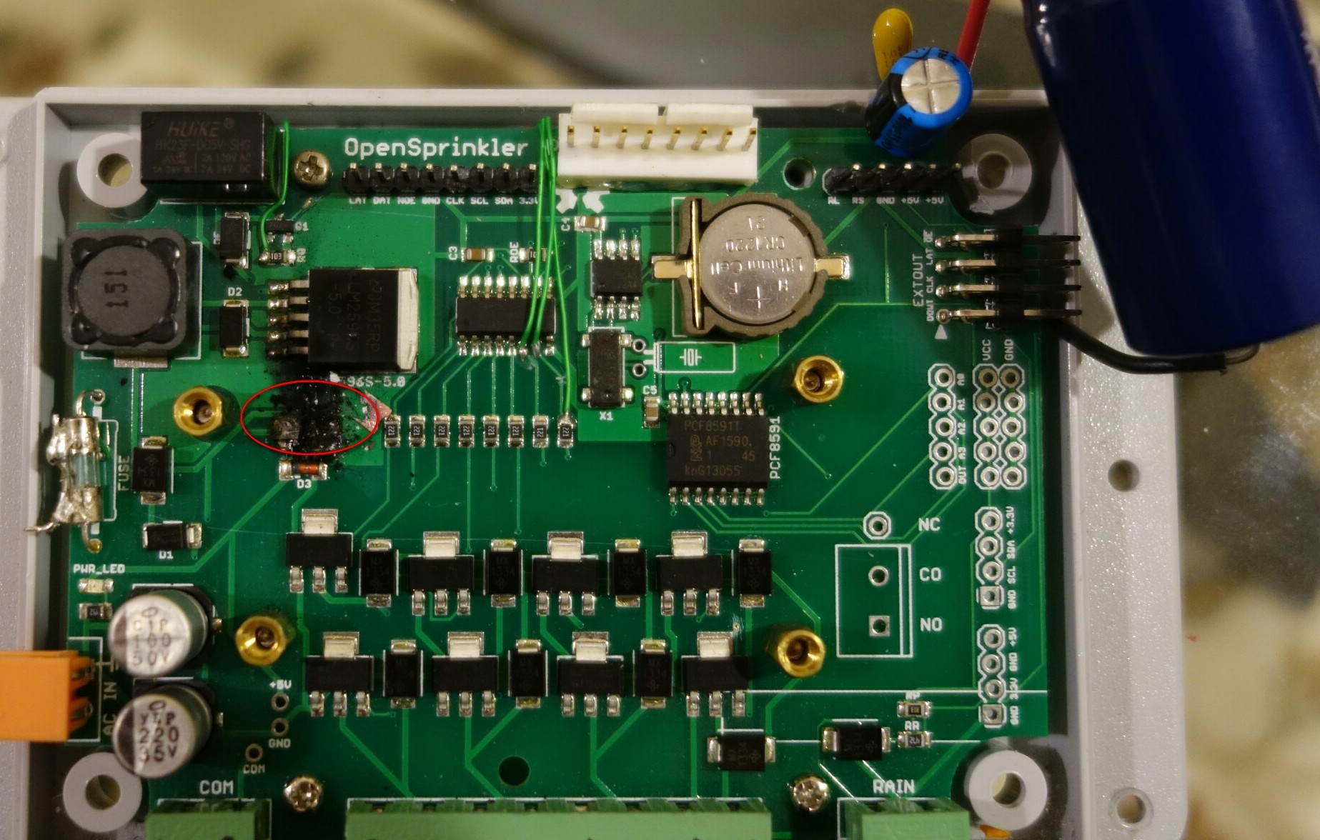
The BOM for v1.3 is not at http://goo.gl/4Nrvb and the EagleCAD silk screen also doesn’t say anything on the blown part (see attached – the charred area between LM2596S-5.0 and 5.6V zener (D3). Is this a fuse and what value and part #? No info on the sch. file either.
I blew this part *probably* because I added a nearly 5000uF cap on the +5V?? Maybe it’s the surge current to charge the cap that blew it although I am surprised since it shouldn’t be that much. I will try moving this cap before the LM2596 to see if that might help. (It seems like the 2A fuse also blew — totally inexplicable!)
Had to do this since there is a 120VAC pump motor that puts a dip on the line voltage that travels all the way to +5V and freezes the RPi and other electronics.
Any technical advice would be deeply appreciated.
Thank youAttachments:
July 28, 2015 at 10:26 pm #39555
RayKeymasterThat’s a 1.5 amp PTC fuse (surface mount 1812 size). It’s for protecting the 5V line supplied to RPi. I am very surprised the PTC fuse is burned — I’ve never seen such a case. Why do you need a 5000uF capacitor? It looks really huge.
July 28, 2015 at 11:13 pm #39557
4worldParticipantI am surprised too. I will investigate further why the fuse blew by doing some calculations for the cap, current, etc.
The reason I need the 5000uF cap is as said before: I have a 120VAC pump motor that is turned on by the RPi+OSPi. When the pump turns on, it sucks a large AC current which momentarily drops the 120VAC big time. This drops the 24VAC which in turn drops the +5VDC momentarily — this dip is enough to cause the software to go haywire. I don’t have my storage scope here so won’t be able to investigate exactly how big the dip is but will in any case try using a smaller cap to see if that does the job.
Do you know where I can get a replacement for the 1.5A PTC fuse or is it generic enough to get at Radio Shack, Amazon, etc.?
Thanks for your time.
July 29, 2015 at 10:13 pm #39577
4worldParticipantRay,
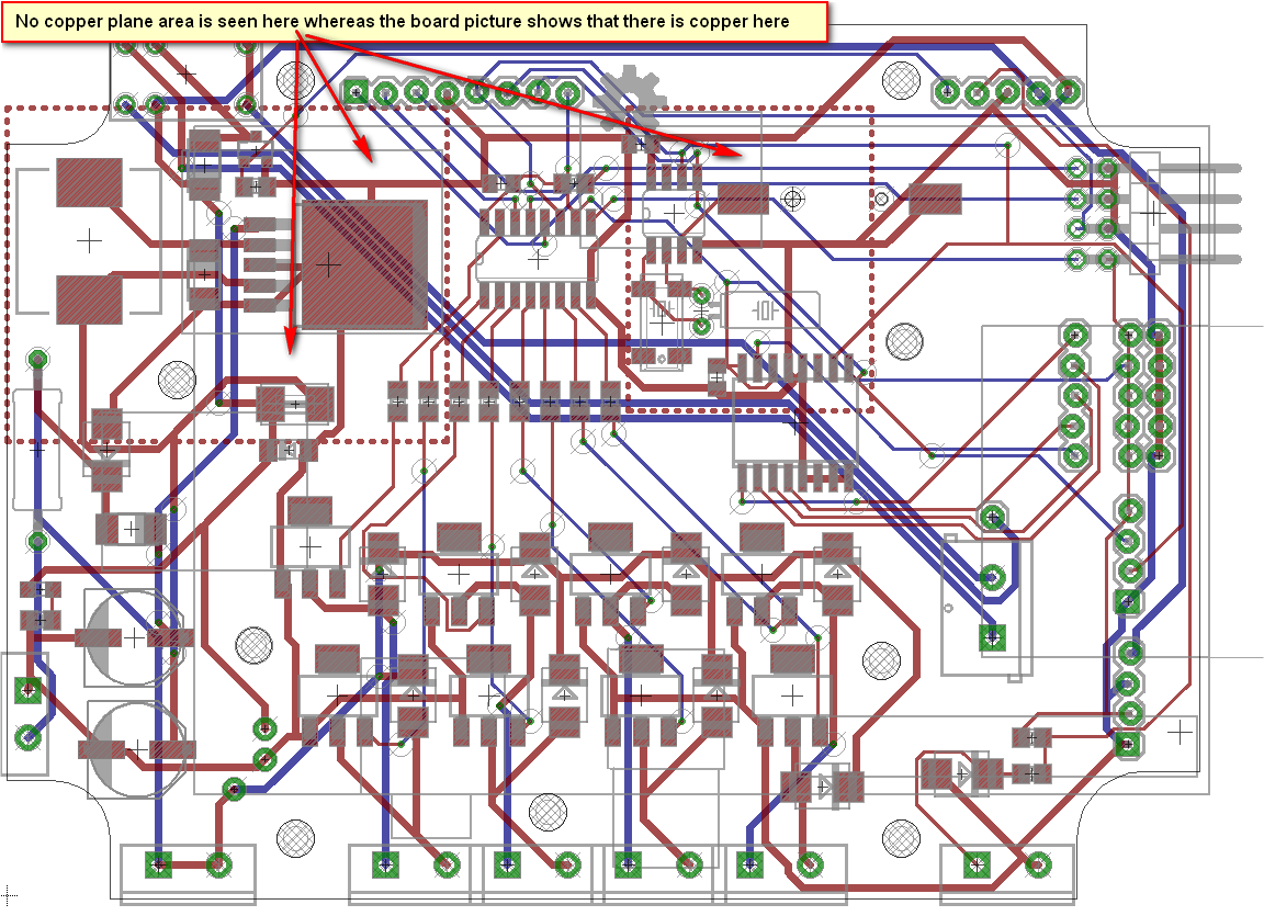
The github PCB layout files for OSPi V1.3 (.BRD) do not show the copper areas that can be seen on the actual V1.3 board. In fact the copper traces are also quite different.
With the literal blow out of the PTC fuse which has ripped apart some traces also, I need to see the actual layout so I can repair the tracks.
Please help…
Thanks
July 29, 2015 at 11:23 pm #39578
RayKeymasterIt’s pretty easy to find. For example, this one from Digikey:
http://www.digikey.com/product-detail/en/0ZCG0150BF2C/507-1773-1-ND/4156304July 30, 2015 at 10:12 am #39580
4worldParticipantThanks Ray. Please answer the ultra-important message above as I am stuck without it. Repeated below —
The github PCB layout files for OSPi V1.3 (.BRD) do not match the actual V1.3 board I have. E.g., the BRD file doesn’t show copper plane areas even with all layers turned ON in Eagle CAD. In fact even the traces are different.
With the literal blow out of the PTC fuse which has ripped apart some traces also, I need to see the actual layout so I can repair the tracks. Where is the accurate layout file or image?
Thanks
July 30, 2015 at 3:04 pm #39585
RayKeymasterI don’t know what you mean. I downloaded those files and they look fine in my EagleCAD. I think you probably downloaded the files by using ‘save file as’ on the file name. The correct way is to either download the entire repository and unzip it, or use the ‘Raw’ file link:
https://github.com/rayshobby/opensprinkler/raw/master/OpenSprinkler%20Pi/hardware/ospi_v13.sch
https://github.com/rayshobby/opensprinkler/raw/master/OpenSprinkler%20Pi/hardware/ospi_v13.brdAugust 3, 2015 at 7:48 pm #39651
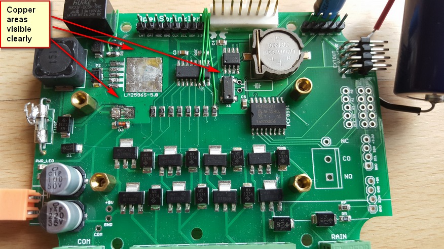
4worldParticipantThe files you point to are the same ones as I downloaded.
Please see the attached two pictures — one is a screenshot from EagleCAD with all relevant layers turned ON and the other is the OSPi v1.3 board that I have. See the arrows and you can clearly see that the two layouts are different at least as far as copper areas go.
Awaiting your response.
Thanks.
August 3, 2015 at 9:21 pm #39654
RayKeymasterOK, I thought you meant EagleCAD reports that the schematic and board do not match. Well, is it critical that the traces have to match your board? There may be some slight differences but the schematic is pretty much the same. Which wires are you trying to figure out?
August 3, 2015 at 9:37 pm #39656
4worldParticipantFirst, I need to solder the blown PTC fuse and since it literally exploded, the pads/traces in that area are gone.
Second, I may need to replace other blown components (like maybe the LM2596), zener, etc. <– This I can figure out if you confirm that the only differences in the above two layouts is just the copper area.
Ray, thank you again for your excellent support.
August 5, 2015 at 1:53 pm #39684
RayKeymasterI am pretty sure the schematic is the same, despite the fact that the board layout is different. From the schematic you can tell that one end of the PTC fuse is connected to the positive pin of capacitor C2, the other end is connected to VIN (i.e. +5V).
You should also make sure to check the zener diode D3 and the RTC DS1307. The reason is that if there has been an overvoltage situation, D3 is likely burned and DS1307 is also likely damaged. So before you power on by 24VAC, use a multimeter to check the resistance between VIN-GND. That resistance should be at least 4.5 kilo-ohm. If it’s below that, some other components on the 5V line may have been shorted.
-
AuthorPosts
- You must be logged in to reply to this topic.
OpenSprinkler › Forums › Hardware Questions › OpenSprinkler Pi (OSPi) › OSPi Ver 1.3 layout request