OpenSprinkler › Forums › Hardware Questions › OpenSprinkler › Query with the firmware driving of the DC board
- This topic has 6 replies, 2 voices, and was last updated 4 years, 9 months ago by
marvincide72.
-
AuthorPosts
-
October 4, 2021 at 9:26 pm #71343
marvincide72ParticipantFirstly I would like to say how great your design is. There are a few at my work that have an OpenSprinkler unit.
The main reason I am contacting you is I am in the process of completing a build of three OSv3 – DC sets and am having issues with high current draw after a station has completed its activity, the current draw is ~300mA. Before a station is running from initial bootup the current draw is ~50 to 90mA at best depending on idle behaviour. I would assume that after the completion of all station activity the unit would return to a current draw similar to the bootup value.
I have looked at the schematic circuit and the BVE line stays high after station activity. Just to confirm board behaviour I wrote some Arduino code for a UNO to control the PCA9555 directly without the main board so that I could monitor specific behaviour of current draw when a particular output is enabled HIGH, the BPE & BVE control lines switch on and off fine, but current draw with the BVE line only HIGH gives similar current draw after a station has completed.
With the ~300mA current draw the 7805 is getting extremely hot, this isn’t an issue on initial bootup. Looking at the schematic circuit I am not sure why the 5V rail is having a lot of load when the BVE is HIGH.
Could you please inform me why the BVE control line would need to be HIGH after all station activity?
I have also been able to grab one of my colleagues’ OS3.2 – DC units that he has been using for a year or so and that one is performing the same, the BVE line is HIGH after station activity is completed and the 7805 is getting hot, drawing ~300mA.The following are what the webpage/about screen shows,
Hardware Version: 3.2-DC
Firmware: 2.1.9 (2)
App Version: 2.2.5
I have tried versions of firmware from this one through to 2.1.9 (9) with no difference seen.I have also redrawn the schematic circuit in CircuitMaker, just to make it more readable (attached).
I hope I have made sense for you to understand.
Thanks
Paul HarrisAttachments:
October 5, 2021 at 11:19 am #71353
RayKeymasterI don’t fully understand the problem, but here are a few notes to begin with:
– BPE is the booster power enable pin, when it’s high, the input DC voltage is fed into MC34063 booster to generate boosted voltage.
– BVE is the booster voltage enable pin, when it’s high, the boosted voltage from the 2200uF capacitor is dumped to the COM line, to provide impulse voltage for the solenoids to engage.
– Between the input DC voltage and COM, there is a SS34 diode, this way, as the boosted voltage fades away, the input DC voltage will continue to provide holding current for the solenoids to keep engaged. As long as BPE is turned LOW after the initial impulse voltage, it doesn’t matter if BVE stays HIGH or not, because the voltage from 2200uF will eventually fall below input DC voltage, hence the input DC voltage will take over to provide current to the solenoids. On the other hand if BPE stays high, the booster will continue to try to bump the voltage, and that can be a problem.
– The only thing I can think of, regarding 7805 drawing a lot of current, is that something on the +5V line is drawing a lot of current. But if you look at the schematic, there isn’t that much connected to the +5V line: the booster is connected to the input DC voltage, so that comes directly from the power supply and not drawing from +5V. Also, as long as the input DC voltage is higher than 5V (we use 7.5V by default), the current shouldn’t flow backward from 5V to the input.
– We are aware that if the controller has a wired Ethernet module connected, it can draw a lot of current — because the wired Ethernet module itself draws 180mA, and the WiFi chip further draws 70mA, that’s about 250mA at minimum. For this reason, if wired Ethernet module is connected, we recommend the input DC voltage to be as low as possible: 7.5V is ideal, 9V is probably ok, but 12V would be too high as that will put too much heat dissipation on 7805. Even without wired Ethernet module, the DC voltage should not be higher than 12V, again, to minimize the power dissipation on 7805.What is your input DC voltage? Even at 300mA current, if the input voltage is only 7.5V, that power dissipation shouldn’t be more than (7.5-5)*0.3 = 0.75W (probably a bit lower than this because there is a diode D1 that drops maybe 0.5V). Do you have anything else connected on the +5V line?
October 5, 2021 at 5:59 pm #71360
marvincide72ParticipantHi Ray,
Thanks for the response, your explanation of the design was helpful, you have confirmed my understanding of the way it works.
I am using an adjustable bench supply for the moment set at around 8V. There is no wired ethernet module, just basic original circuit.I agree that its not making any sense that there is a higher current draw with the BVE line left high and that shouldn’t influence the 5V line, I will investigate a bit more.
Thanks
PaulOctober 6, 2021 at 8:38 pm #71366
RayKeymasterI tested the current draw on the 5V line using a OS 3.2 DC, and it’s definitely not 300mA. With the ESP8266 (i.e. top layer board) on, the current is about 80mA in AP mode, and about 50mA in WiFi station mode. This is the case either when no solenoid is on, or a solenoid is on. You said you have a friend who has a OS 3.2 DC, that you tested and it draws about 300mA. I am not sure how to explain that, but the one I tested definitely does not have this issue.
One thing you should be careful with is the SMBJ24A TVS diodes — these are for protection against high transient voltages. These are polarized (unlike in the AC-powered controller, which uses non-polarized TVS where the part number ends with CA and not A): the negative of each TVS diode should be connected to each zone port, and the positive should be connected to the 0.2ohm current sensing resistor. I realized that in the schematic I used a non-polarized TVS diode symbol, so it probably is confusing which direction it is. If the polarity is wrong, when a solenoid is connected, it’s basically immediately connecting the solenoid to ground, thus it will start to draw current even when the zone is off. That said, it still doesn’t quite explain the high current draw on the 5V line, because in holding state, the solenoid draws current from the input power supply, not from the 5V line, so even if the TVS diode polarity is wrong, it still doesn’t explain the issue.
October 7, 2021 at 7:21 pm #71370
marvincide72ParticipantHi Ray,
I have done some more digging into this today, since posting originally to you I noticed that the PCA9555A is also getting extremely hot like the 7805.
– I have a DC board that doesn’t have the PCA9555A fitted so I thought I would do some measurements on this first.
Initially I manually tested driving the bases of QB1 & QB2 HIGH individually, the current draw was as expected, when QB2 was HIGH an initial high current and quick decay as CB is charged. QB1 & QB2 LOW : 6.4mA, QB1 HIGH only : 23mA, QB2 HIGH only : 17mA (after CB charged). QB1 & QB2 both HIGH : 33mA.
– Measuring the above I went back to the board that had the PCA9555A fitted and decided to isolate QB1 & QB2 bases to P1_6 & P1_5 of the PCA9555A by cutting the tracks. Then I manually tested the driving of the bases of QB1 & QB2 HIGH again. All tested the same as when the PCA9555A wasn’t installed. The PCA9555A was also happy, even though its isolated on these pins at that time. A UNO driving the PCA9555A directly for the P1_6 & P1_5 pins behaved normally as well. I decided to measure the base current of QB1 & QB2 when HIGH. QB1 is ~7mA and QB2 is ~10.3mA. (Due to multimeter leads the voltage drop will also give slightly lower current measurements). On checking the PCA9555A datasheet the I(OH) is 10mA (I(OL) is 25mA). So it seems the PCA9555A maybe getting annoyed with this high base current.
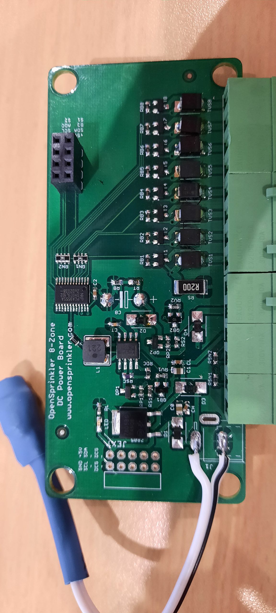
– I decided to fit a current limiting resistor to each of the QB bases. For my transistors fitted I calculated and fitted a 4k22. Once fitted I get normal behaviour with the board now. Connecting the ESP board and fully testing the solenoid activation the currents are what I expected and what you are seeing as mentioned in your previous posting.– I have attached the updated schematic of where the resistors are placed so that we are on the same page of where I have placed them. Also a picture of my board, just so that you can see what board I am using.
– Yes I also found out about the SMBJ24A’s, I have since rotated them on my boards.
– I’m not familiar with the evolution of your boards, do I have an older variant?
Thanks
PaulOctober 8, 2021 at 8:32 pm #71382
RayKeymasterAh, I know what happened — and this is admittedly my fault not updating the part number properly. So QB1 and QB2 originally were MMBT3904 NPN transistors, and as such they should have base resistors (anywhere between 1K to 10K should be ok). However, in the end I decided to minimize the number of different parts so these were replaced by AO3400 N-channel MOSFETs, since the board already uses AO3400. As is there is now only a 10K pull-down resistor between gate and source, there is no more base resistor. So if you used MMBT3904 then it would have no base resistor causing large current draw. I think this is probably what happened. I am sorry about the inconsistency in the schematic and I will update it in github shortly.
October 9, 2021 at 12:43 am #71384
marvincide72ParticipantThanks Ray for the update, all good, at least I know what’s happening differently at my end.
For simplicity I will replace QB1 & QB2 with a FET as well.Thanks for the help 🙂
Paul
-
AuthorPosts
- You must be logged in to reply to this topic.
OpenSprinkler › Forums › Hardware Questions › OpenSprinkler › Query with the firmware driving of the DC board