OpenSprinkler › Forums › OpenSprinkler Unified Firmware › Change Firmware to control stations directly via GPIO pins (relays)
Tagged: 2.2.0(1), ESP12F_RELAY_X4, GPIO, OpenSprinkler-ESP8266-WIFI-4-Channels-Relay-Module-AC-DC-ESP-12F-Development-Board
- This topic has 26 replies, 6 voices, and was last updated 3 years, 1 month ago by
StudioShemp.
-
AuthorPosts
-
March 14, 2021 at 9:48 pm #69430
TobascoParticipantHi,
after my beloved OS Bee died and I couldn’t fix it, I decide to set up a new one based on an “ESP8266 WIFI 4 Channels Relay Module AC/DC ESP-12F Development Board”.The flashing, WiFi connection and OLED Display works already, now I want to change the firmware to control the 4 relays via the GPIO pins
- GPIO16 (D0)
- GPIO14 (D5)
- GPIO12 (D6)
- GPIO13 (D7)
May you give me a hint, which part of the code I have to change so that Station 1 to 4 is linked to this GPIO pins?
salute
ThomasMarch 15, 2021 at 11:00 am #69440
TobascoParticipantHi,
I solved my problem by replacingapply_all_station_bits()with custom code to control the GPIO pins for the relays:void OpenSprinkler::apply_all_station_bits() { const uint8_t stationGPIO[] = {16, 14, 12, 13}; for (uint8_t i = 0; i < 4; i++) { pinMode(stationGPIO[i], OUTPUT); digitalWrite(stationGPIO[i], station_bits[0] & 1 << i ? HIGH : LOW); } }salute
ThomasSeptember 22, 2022 at 12:16 pm #73967
GompkaParticipantHello Thomas,
can you elaborate on which file in the firmware this line of code should be changed? Is it in opensprinkler.h?
September 22, 2022 at 12:25 pm #73968
TobascoParticipantHo Gompka,
it’s in the fileOpenSprinkler.cpp, just search forvoid OpenSprinkler::apply_all_station_bits() {You can find a fully working variant for the ESP8266 WIFI 4 Channels Relay Module on my Github account (with more information about the hardware setup):
https://github.com/ThFischer/OpenSprinkler-for-ESP12F_Relay_X4#readmesalute & happy engineering
ThomasSeptember 22, 2022 at 12:33 pm #73969
GompkaParticipantThanks for the quick reply, I will definitely take a look at the github. I was running a raspberry pi which failed and figured I would move to esp8266 since I have plenty of them.
September 22, 2022 at 12:35 pm #73970
TobascoParticipantGood choice!
A Raspberry PI is kind of oversized just to run Opensprinkler.There is also another branch where I used a normal NodeMCU Lua Lolin V3 and a 8Ch Relay board:
https://github.com/ThFischer/OpenSprinkler-for-ESP12F_Relay_X4/tree/NODEMCU_74HC595/NodeMCU-74HC595#readmeNovember 25, 2022 at 9:15 am #74383
vampParticipantHello there
I dont know how is the maintainer this github branch, (maybe Gombka?) but refer this forum theme.
My question is:
Are you plan to update to (11) your code? The Weather check error, that fix the 11 version is also affect to me. It would be good that update it.
Thanks a lot!!
March 30, 2023 at 4:05 am #75128
vampParticipantHello there,
I maked 2.1.9(11) update to ESP8266-WIFI-4-Channels-Relay-Module-AC-DC-ESP-12F-Development-Board. (based solideus FW)
I tested it, work well. (OTA is working, i simply update (2.1.9(9))
I also checked 2.2.0(1) but it to much to me… It rewrite a lot of things, it need to re-implement from scratch.
March 30, 2023 at 4:48 am #75129
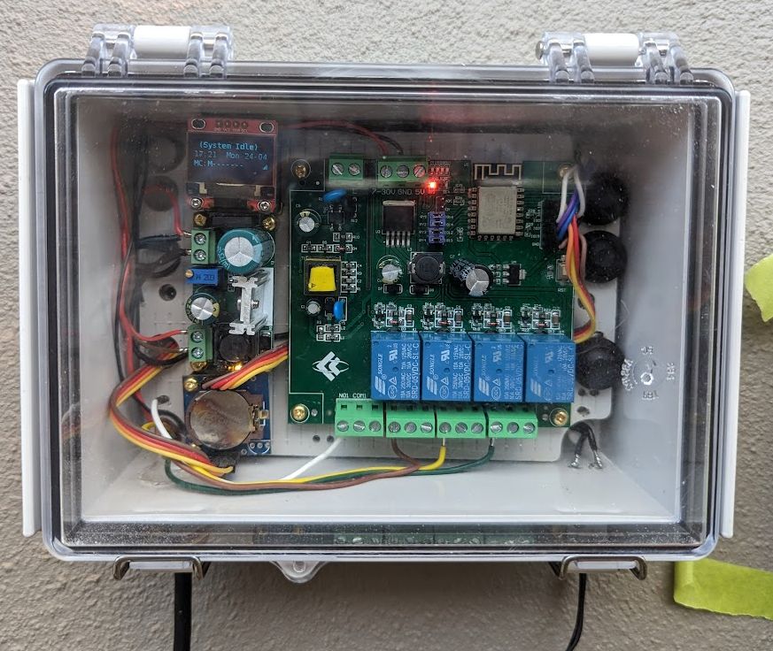
vampParticipantI think that try this FW on 8 relay board. If i change this, is enough?
From:
#if defined(ESP8266)

  if (ESP12F_RELAY_X4) {

		// On the ESP12F_Relay_X4 board the relays for station 1...4 are connected to GPIO 16, 14, 12 and 13:

		const uint8_t stationGPIO[] = {16, 14, 12, 13};

		for (uint8_t i = 0; i < 4; i++) {

			pinMode(stationGPIO[i], OUTPUT);

			bool isActive = station_bits[0] & (1 << i);

			digitalWrite(stationGPIO[i], isActive ? HIGH : LOW);

		}

		return;

	}
To:
#if defined(ESP8266)

  if (ESP12F_RELAY_X8) {

		// On the ESP12F_Relay_X8 board the relays for station 1...8 are connected to GPIO 16, 14, 12, 13, 15, 0, 4 and 5:

		const uint8_t stationGPIO[] = {16, 14, 12, 13, 15, 0, 4, 5};

		for (uint8_t i = 0; i < 8; i++) {

			pinMode(stationGPIO[i], OUTPUT);

			bool isActive = station_bits[0] & (1 << i);

			digitalWrite(stationGPIO[i], isActive ? HIGH : LOW);

		}

		return;

	}
The Board:
March 30, 2023 at 5:08 am #75130
TobascoParticipantHi Vamp
> I think that try this FW on 8 relay board. If i change this, is enough?Looks good for me (if your GPIOs are correct).
salute
ThomasMarch 30, 2023 at 8:40 am #75132
vampParticipantMarch 30, 2023 at 8:56 am #75133
TobascoParticipant@Vamp
> So not need to change any other line in this file or any other, right?It depends on how the other GPIOs are connected on your “ESP12F_Relay_X8” board!
Just check all my changes by searching for “#ifdef ESP12F_RELAY_X4”
For example I changed
– “V2_PIN_BUTTON_3” from “IOEXP_PIN+12” to “15”
– “V2_PIN_RFTX” from “15” to “IOEXP_PIN+12”See also my change in gpio.cpp at “if (BUTTON_3_PULLDOWN && pin == PIN_BUTTON_3) {”
salute
ThomasMarch 30, 2023 at 9:04 am #75134
TobascoParticipant@Vamp
… and also check, which GPIOs OpenSprinkler is using.
None of them must collide with the GPIO usage on your “ESP12F_Relay_X8” board!
The GPIO allocation of your board is shown at https://templates.blakadder.com/ESP12F_Relay_X8.htmlsalute
ThomasApril 26, 2023 at 8:41 am #75421
StudioShempParticipantHi all,
I’ve created a version 2.2.0(1) build of the firmware at https://github.com/StudioShemp/OpenSprinkler-ESP8266-WIFI-4-Channels-Relay-Module-AC-DC-ESP-12F-Development-Board
I essentially compared and isolated the changes from the original 2.1.9(11) release by OpenSprinkler with the 2.1.9 release by @vamp mentioned in this forum (branched from solideus merge on github) and embedded these changes in to a clean 2.2.0(1) codebase from OpenSprinkler.
I have tested it on my ESP12F_RELAY_X4 build (ESP8266-WIFI-4-Channels-Relay-Module-AC-DC-ESP-12F-Development-Board) and everything is working well, noting that you will need to back up first then restore, as this release will perform a factory reset.
I’ve also made a few enhancements to make maintaining easier for new releases – created a ‘define’ in defines.h to flag the use of the ESP12F_RELAY_X4 board, and altered the code in main.cpp, OpenSprinkler.cpp and defines.h to read this flag to run the code specific to the ESP12F_RELAY_X4 board depending on the value of that flag, 1 or 0, in defines.h. (the standard 2.2.0(1) executes if the flag is set at 0). All sections of code using the flag as a condition are commented with /**ESP12F_RELAY_X4… */
For this version (2.2.x) you will need to:
manually install the OpenThings-Framework-Firmware-Library into your Arduino IDE’s library folder
(https://github.com/OpenThingsIO/OpenThings-Framework-Firmware-Library)install the WebSockets Library by Markus Sattler using the Library Manager in the Arduino IDE
There’s a pull request now on the solideus github repo for my Master 2.2.0(1) branch.
As a bonus, there’s code in there to alter the date format to DD-MM on the LCD (another flag in defines.h) for those of us who don’t use (or like!) the US MM-DD Date format .
All running beautifully on my build. Thanks to @Tobasco, @Vamp and solideus for the awesome effort on this.
Cheers,
StudioShemp
Attachments:
April 26, 2023 at 8:41 am #75426
RayKeymasterThank you for sharing your work. It’s much appreciated!
April 26, 2023 at 8:56 am #75428
TobascoParticipantHi StudioShemp,
good job!Since I mentioned in my repo some hardware related things (DS1307 changes, snubber, antenna improvements) which may also valid for people who visit your repo, it may be better to set a link to my repo in your README.md
salute
ThomasApril 26, 2023 at 5:10 pm #75434
RayKeymasterCan you point to me where you mentioned snubber, antenna improvements? I saw that you mentioned DS1306, interesting, I didn’t know the existence of DS1306. DS1307 has always been the most popular RTC, though I’ve changed to use PCF8563 due to its lower cost.
April 26, 2023 at 5:37 pm #75435
StudioShempParticipant
@Ray, Tobasco’s repo is at https://github.com/ThFischer/OpenSprinkler-for-ESP12F_Relay_X4I’ve just updated my README.txt as per his suggestion to include the tips he mentions above (and acknowledge his foundational work for this project). I wish I’d found the repo earlier and forked from it as it’s far more aligned to where I headed in my own.
Also wanted to mention the LCD/OLED date format change in my repo, and wondering if something similar could be included as an option in the OpenSprinkler GUI for all of us that use DD-MM date format in our part of the world and simply cannot fathom MM-DD when we see it.
Finally, I just wanted to say thank you for supporting those of us who love to tinker with alternative hardware.
Cheers,
StudioShemp
May 2, 2023 at 3:51 pm #75503
TobascoParticipantHi @Ray,
it’s time to say “Thank you” for sharing your generally work on OpenSprinkler and for sharing this effort as open source/hardware.It brought me back to my 40 years ago roots of hardware tinkering and was a big benefit!
salute
ThomasMay 8, 2023 at 9:23 am #75573
vampParticipantHello @StudioShemp !
I would like to use your code a 8 relay board. 4 relay conflict with two button and the two display gpio. But this functions are not needed. I would like to comment out this. Please help me, where find the button and screen gpio in source code.
Thanks!
May 8, 2023 at 9:46 am #75575
TobascoParticipant@vamp
You may also consider to use a simple shift register as a port expander like I did in this project branch
https://github.com/ThFischer/OpenSprinkler-for-ESP12F_Relay_X4/tree/NODEMCU_74HC595/NodeMCU-74HC595#readmeJust search for NODEMCU_74HC595 in the source code to see the necessary changes
salute
ThomasMay 8, 2023 at 10:06 am #75576
vampParticipantWe are already bought the 8 relay board, so first we would like to use this ones. and really not need the buttons and the display, so would be good to use this GPIO-s
May 9, 2023 at 12:09 pm #75601
RayKeymasterOne issue with using all GPIO pins is that some pins must be held at certain state during power-on, while others can have a moment of glitch during power-on. For example, GPIO2 must remain high at power-on, GPIO15 must be low, and GPIO16 starts as high but flickers for a couple hundred milliseconds. So these GPIOs, when connected to relays, can produce moments of false action of the relays, albeit this only happens at power-on or reboot. If this can be tolerated, then you can use all GPIO pins.
May 18, 2023 at 10:54 am #75715
vampParticipantGuys help me a bit, i can not found what need to delete/comment it to able to use i2c (display) and button pins to control more relays. i found where set the gpio-s to relay, but now is colliding to two button and the display gpios.
I use this repo:
May 19, 2023 at 9:08 pm #75730
StudioShempParticipantHi @Vamp,
For the buttons – You’re going to have to examine how you’ve set PIN_BUTTON_1, PIN_BUTTON_2, PIN_BUTTON_3 in your defines.h and where they are used in the code to ensure that when the relays are triggered, the code isn’t reading the same pin e.g. digitalReadExt(PIN_BUTTON_xx).
The display is far more embedded. If I recall, the code already handles detection of a display if present, but if you’ve tried using the SDA (GPIO4) / SCL (GPIO5) pins already and it hasn’t worked, you may need to remove references to it in the code, e.g. remove the #include statements for the display library (SSD1306Display.h). If you still have issues, possibly comment out sections of code which call the display library -e.g. lcd.init(); or write to or clear the display (lcd_print… etc. )
Using the display pins goes beyond what I was aimig to do, so I can really only provide general guidance here.
Also – you need to be aware of what Ray mentions above – the behaviour of the pins and their default states at power-on. You will need to look at the esp8266 reference material for the expected default states of the pins you’re intending to use and see if your use is consistent. If not, you may find the module doesn’t even power on.
I hope that helps.
-
AuthorPosts
- You must be logged in to reply to this topic.
OpenSprinkler › Forums › OpenSprinkler Unified Firmware › Change Firmware to control stations directly via GPIO pins (relays)