Forum Replies Created
-
AuthorPosts
-
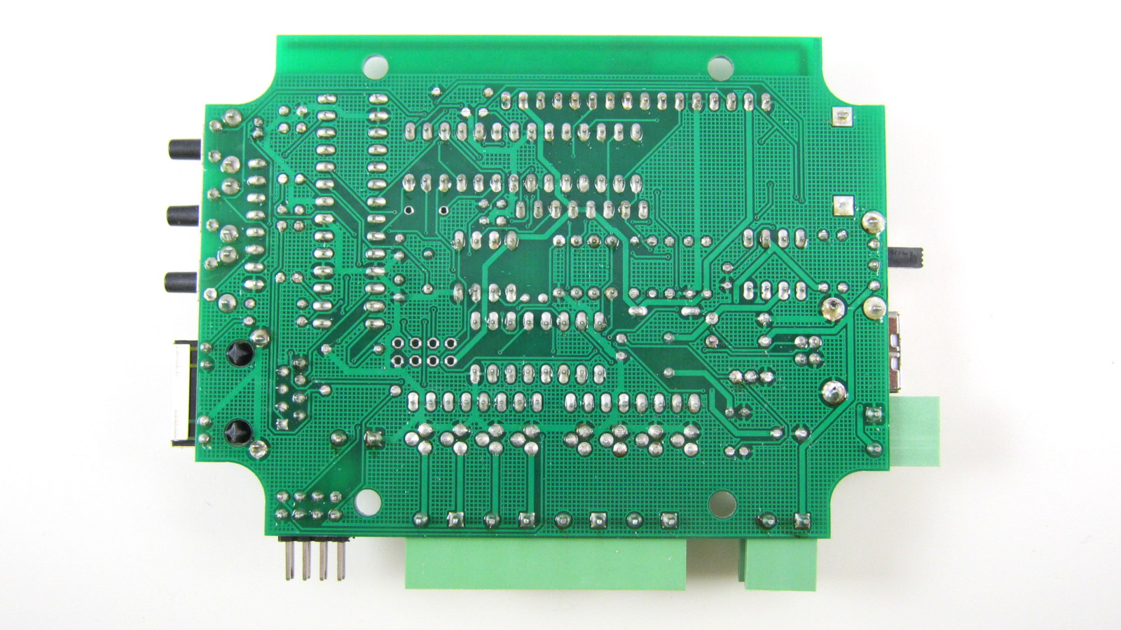
RayKeymasterIt’s difficult to pinpoint the exact reason without seeing your board and soldering quality. Here is a reference image of the soldered board:
http://rayshobby.net/wordpress/wp-content/uploads/2013/04/svc142_build_back.jpgThere are a few tests you can start with:
– measure the resistance between VIN and GND, and also VCC and GND. If any of them is small (less than kilo-ohm level), there is probably a short somewhere.
– since your IC1 is burned, you should also check the related elements, particularly D1, D2, D3, and see if they have been damaged in any way. To check these diodes, use a multimeter to measure the forward drop voltage. D1 and D3 should have 0.5-0.7V, and D2 should have around 0.2V. If the forward drop voltage is shown to be close to 0, the diode is burned and needs to be replaced.
– Try to power the circuit board through USB and measure the voltage between VIN and GND, and also VCC and GND, see if they are roughly 5V and 3.3V respectively.Regarding the three 220uF capacitors, I apologize for the issue. Just to make sure: since the 220uF and 10uF capacitors are very similar in appearance, did you check the label on the capacitor body to see they are actually all 220uF?
Thanks for pointing out the missing Rain Sensor step. Will add that to the instructions later.
RayKeymasterThat’s right — the nice icon has been removed in 1.8.3 to save program memory space 🙂
RayKeymasterThe backlight is hard wired so there is no way to turn it off. It may seem a waste but the power consumption is actually less than 10mA.
The upcoming 2.0 has backlight controlled by PWM so the brightness can be adjusted.
RayKeymasterOne quick question: everyone who encountered issues with 2.0 development board: could you check the PCB and let me know if you have a black PCB or green PCB? They have slightly different schematics. If I can identify it’s always the green version that leads to the issues, that can help me narrow down the problem. Thanks.
RayKeymasterThat looks like a problem with bad crystal oscillator. Will send you a replacement right away.
RayKeymasterIt sounds like there is a problem in reading the time values from DS1307 RTC. I will check the schematic and the firmware to see if there is any bug there. If it can’t read time reliably, that may be the cause of controller becoming irresponsive.
By the way, could you tell me if your controller has a black PCB or green PCB?
RayKeymasterIt is supposed to show your local time. After you changed time zone, did you restart the controller? Every time you change the time zone, you need to restart the controller so it can grab the correct time from the Internet.
RayKeymasterOK, keep me updated. As I am going to officially release 2.0 soon, it would certainly be good for me to iron out any technical issue quickly. Thanks.
RayKeymasterOK, if anyone can please send me back your OpenSprinkler 2.0, I will take a look and diagnose the problem. I have a 2.0 board at hand and I have not encountered a similar problem. Please contact me directly at [email protected]. Thanks.
RayKeymasterI can add this to the todo list, but to be honest, detecting conflict is not as easy as it appears: the conflict may happen at some arbitrary day in the future (say if one program is a weekly schedule, one is an interval day schedule), so even with an algorithm to automatically detect this, it will have to simulate through a potentially large number of days until it finds a conflict.
RayKeymasterIf you just want to quickly scale up/down the water time, you can use the ‘Watering Level’ option. It defaults to 100%, but can go anywhere from 0% up to 250%. The watering percentage will be multiplied with the program’s water time, so it’s a quick way to adjust water time globally.
RayKeymaster@Benoitm234, glad to hear that it worked finally, and thanks in advance to help spread the word.
By the way, I have recently set up a Wiki page for Rayshobby, in order to host user-contributed content. This is suggested by Andrew from Australia. He wrote down some initial notes about how to set up RPi to work with OSPi. The Wikipage is at this link:
http://rayshobby.net/mediawiki/We will gradually refine the Wikipage, and hopefully it will receive more community support from users.
RayKeymasterIt doesn’t have such a feature yet. Will put it on todo list. In the meantime, note that each program can be individually enabled or disabled. So you can add two sets of programs, one for the summer, one for the winter. To switch, just enable all programs in one set and disable those in the other set.
RayKeymasterThere may be a stability issue that I am not aware of (although I have a test 2.0 circuit that has been running weeks without a problem). Do keep me updated about your findings.
RayKeymasterYou are right, there is no rain sensor connector on board. There is not much room to put another connector, and also the ultimate goal is to make use of online weather data to detect rain.
If you want to add a rain sensor connector, you can use any of the available GPIO pins. Just connect the rain sensor (which has two wires) between teh GPIO and GND. Make sure to set the pin to input, and you may want to add a pull-up resistor if the GPIO pins do not have internal pull-up.
RayKeymasterDenny,
To diagnose the problem, could you please first specify which version of OpenSprinkler you have, and whether it’s DIY or fully assembled?
RayKeymasterIn manual mode, the normal programs will stop running. This is explained in the online user manual:
http://rayshobby.net/?page_id=730#manualManual mode is mainly designed for users who want to use another device to control OpenSprinkler through HTTP commands. If you want the controller to automatically turn back to program mode after a manual session, please consider using the Run-Once program.
RayKeymasterThe traic has a maximum continuous current of 800mA, so it should be able to run two valves together.
RayKeymasterAs additional information, this page contains some tips on sprinkler valves:
http://rayshobby.net/?page_id=207#sprinkler_valves
RayKeymasterIngo,
The USB is only used for flashing the microcontroller, it cannot be used for communication.
For interfacing with other automation systems, the easiest way is probably through the HTTP GET commands:
http://rayshobby.net/?page_id=730#httpget
RayKeymasterAll commands are implemented with HTTP GET command, including Enable/Disable Operation. For example:
http://x.x.x.x/cv?pw=opendoor&en=0
will disable the controller. For details, please check this section of the user manual:
http://rayshobby.net/?page_id=730#httpget
RayKeymasterSure, that’s a good suggestion. Will put it on my todo list.
RayKeymasterAlready replied to you.
RayKeymasterWell, you can tell if the controller crashes when running a particular zone. OpenSprinkler currently does not have circuitry to automatically detect defective solenoids, so you need to find it out manually. I don’t have much experience with defective solenoid, but I guess there are quicker ways to test, such as testing the coil resistance (if the resistance is too low compared to other good solenoids, that indicates a problem).
RayKeymasterThe first thing to try is to unplug the common wire terminal (so the solenoids will not be activated) and see if the controller still crashes. If not, that means the problem is either a defective solenoid, or the PTC fuse under high temperature (as discussed in this thread: viewtopic.php?f=9&t=84). If the controller still crashes even after the common wire is disconnected, you should return the controller for a replacement. Send email to [email protected] for support.
-
AuthorPosts