Forum Replies Created
-
AuthorPosts
-
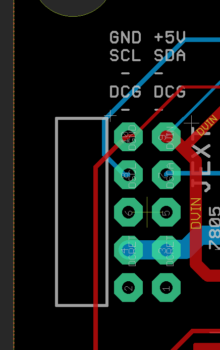
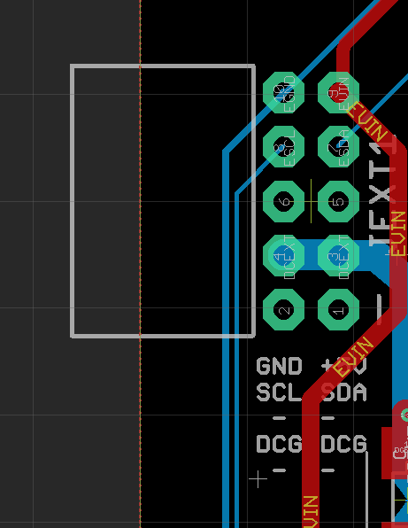
RayKeymasterOn the DC controller and expander, only 6 (in fact, technically only 5) wires are used out of the 10-pin cable. The Eagle design files of all versions are in github, maybe you were looking at the wrong github, but the correct link is here:
https://github.com/OpenSprinkler/OpenSprinkler-Hardware/tree/master/OS/3.0/DC_driver
I’ve attached two images showing the 10-pin connector on the controller, and also on the expander, so you can figure out exactly which pins are used, and the ordering of pins. When I say ‘technically 5’ I mean the DCG (DC ground return) occupies 2 of the pins, so technically if you are short of wires you can just use either one of them.Please note that in contract to expander 2.x, expander 3.0 uses I2C, so there is no DAT, CLK, LAT, NOE etc., instead, it has SDA, SCL.
Attachments:
RayKeymasterWhat firmware version does it have?
RayKeymasterYes, we are working on integrating MQTT that’s currently a pull request in github. Sorry that it has been taking a while — due to the pandemic, we are short staffed and are behind. But will hopefully catch up soon!
RayKeymaster@AKADAP: from my experience, 20ohm for solenoid resistance should be ok — please note that solenoid is a big inductor that has reactance to AC current, so even though the resistance seems low, it actually has a much larger impedance to AC current. In any case, if you found that the resistance is significantly different from your other solenoids, then I think it’s fair to say that indicates a problem.
- Thanks for pointing out solid state relays — I was fully aware of it but made a conscious decision not to use them, for several reasons. One, several years ago when I first started working on the project SSRs are quite expensive, like 3 to 5 bucks each piece — while it’s feasible to use them in a DIY project, using them in massive production will significantly increase the cost. It’s not just BOM cost — manufacturers always add some percentage of margin, also customs duty tax is based on declared value, so that can end up increase the cost by several folds. I agree that now they are much cheaper than several years ago, still there are challenges with choosing them — a lot of SSRs with sufficiently high on-state current (i.e. more than 500mA) have relatively low breakdown voltage (<=40V), which put them at the very edge of acceptable range (24VAC adapter often has no load voltage measuring up to 30VAC, so the peak voltage can exceed 40V).
- Besides, I’ve taken apart many commercial controllers, and all of them universally use triacs — I have never seen any that uses SSRs. Some use opto-couplers to drive triacs, which provide isolation; some use much bigger triacs which can withstand more power dissipation. But frankly none of them alone prevents triacs from burning out due to solenoid shorting, or damage due to lightening. Opto-couplers or SSRs do provide isolation, but that doesn’t mean the triac or SSR itself cannot be damaged. If some zones stop working, either we have to repair the circuit, or toss it out and provide a replacement. At least with triacs they are cheap to replace. If I had to take a guess, I would think the bigger companies that make sprinkler controllers probably realized there is a cost-benefit tradeoff — triacs are crude but they are at a fraction of the cost of SSRs. If adopting SSRs increase the reliability by 10% but adds cost by 50%, it might not be worth it.
- When circuits are produced in large quantity, there are always things that can go wrong in ways that you may never have thought of. For example, I’ve seen relays that don’t click or don’t make contact when clicking. I’ve seen controllers that work perfectly fine when we tested but just won’t work at the customer’s end. While SSRs seem like the perfect solution, I fear that there are other issues entailed by it that I may have not even thought of.
- So, I agree that adding fuse is a very cost-effective solution. Resettable fuse unfortunately does not really work in this setting: they trigger slowly and do not respond well to instantaneous current spikes. Also, as I explained above, users who want to turn on multiple solenoids at the same time do not want to undesirably trip the fuse. Another solution I have seen on some other sprinkler controllers is a big-ass power resistor,like cement resistor, in series with the COM line, to limit current upon solenoid shorting. This is something interesting to try, though picking the exact resistance value is just as difficult as picking the right fuse rating. So in the end, I think it may be best to leave this as an external component that’s easy to replace, as opposed to making it a built-in component on the circuit board.
- Anyways, all that I am trying to say is that I’ve put thoughts into various ways to improve the circuit design, and in the end made the conscious decision to stay with its current form. The decision is not made solely based on reliability, but there are economic considerations. If you are worried about reliability, I do recommend adding an external fuse, or use an external relay board like pcichocki described or shown in this post. I hope this makes sense.
sorry about using bullet list — for some unknown reason bbpress is removing all my line breaks, so had to use bullet list to force line breaks.
RayKeymasterPlease note that in the command you ran, ‘_U’ is a typo, it should be ‘-U’ — i.e. a dash, not a underline.
Also, what follows that is NOT ‘flash:wos_219.hex’, it should be ‘flash:w:os_219.hex’. It’s better that you copy-paste the command from the instructions:
https://openthings.freshdesk.com/support/solutions/articles/5000832311-opensprinkler-2-x-firmware-update-guide
which will reduce the chance of error in typing the command.
RayKeymasterYes, ESP-07S is the version of the chip that has a connector for external WiFi antenna. Please note that replacing the chip yourself would require surface mount rework tools such as hot air gun.
RayKeymasterI think you may be overthinking. Note that 24VAC transformer is always isolated from the mains — the two wires coming out of the transformer, neither of them has galvanic connection to the mains, or the earth ground. So the ‘GND’ on OSPi is just a logic ground, it has no connection whatsoever with the mains or the earth ground. If you are worried that the USB’s ground is earth ground, that’s totally fine, all that this means is it’s going to tie OSPi’s GND to earth ground, but there is nothing wrong about that.
When you have two circuits (such as OSPi and RPi), it’s typical that the ground of both circuits are shared — this is important for all the logic level signals to work. If their grounds are not shared, the voltages would be referring to different reference points, and the two circuits cannot work.
You said “‘GND’ lead from that supply is not actually at ground potential” — I don’t know what you mean by ‘ground potential’ — did you mean logic ground, or earth ground?
RayKeymasterAre you sure this is caused by solenoid shorting? 20ohm resistance is within acceptable range. The damage could be caused by power surges, or voltage spikes induced by lighting etc.
About fuse: it’s difficult to decide the fuse rating — many users want to open multiple solenoids at the same time, which will trip the fuse undesirably. So we can’t decide whether the fuse rating should be 500mA, 1A, 2A or what. We’ve had batches of OSPi in the past that have on-board fuse, but there are false triggerings so in later batches we decided to leave this as a choice for the user — if you want to add a fuse, you can decide what’s the current rating you want.
The triacs we use (Z0103MN) has on-state maximum current of 800mA to 1A, which is in its datasheet:
https://media.digikey.com/pdf/Data%20Sheets/ON%20Semiconductor%20PDFs/Z0103_107_109MN.pdf
All transistors have specified maximum on-state current. This has nothing to do with over-current protection. The maximum on-state current refers to the maximum amount of current that each transistor is able to handle, beyond that it might burn out. Nowhere in the user manual did we say there is over-current protection of 800mA on each channel. The total over-current protection of 2A was from the previous batch when there was on-board 2A fuse, so I admit that’s no longer there and should be removed. Over-voltage protection is done by TVS diode for each zone, that’s for voltage protection, not for current protection.Non-fuse based current limiting circuit for each zone is not trivial to implement and will significantly increase the cost of the circuit. If you have any idea how to implement non-fuse based current limiting circuit for each zone, and this is for AC current, let me know, I would be curious to know.
RayKeymasterThe return is in JSON format. What programming language do you use? Most modern programming languages support parsing JSON data, like Python, Javascript etc. Once parsed, you can access sn1 as a variable of the parsed object (like object.sn1).
RayKeymasterRain gauge is currently not supported: at least not supported if you want to use it to stop watering when a certain amount of rain is received. Technically rain gauge works like a flow sensor — the reed switch internally turns on and off repeatedly to indicate the rate at which rain is accumulated. You can use rain gauge in the sense that you treat it like a flow sensor and you can check its reading. But you can’t use it to automatically trigger the stop of watering because such functionality is not implemented.
RayKeymasterFrom the symptom it’s not obvious to me what’s the cause. This has nothing to do with I2C because OSPi does not use I2C for controller valves. It uses a shift register (74HC595). Some basic things you can check is the VIN-GND voltage (these pins are available at the top-right corner of the PCB). It should be about 5V when it’s powered.
May 1, 2020 at 12:18 pm in reply to: App cannot find new device and cannot manualy input device #65597
RayKeymasterThe IP address in the user manual is just an example, the actual IP address assigned to your controller is different. Can you open a browser and type in the following:
http://x.x.x.x/ja?pw=a6d82bced638de3def1e9bbb4983225c
where x.x.x.x is your controller’s IP (i.e. the IP you see when you press B1). The password (pw) is the md5 checksum of the default password (opendoor). If you have changed the password to something else, you can use https://www.md5hashgenerator.com/ to compute the md5 checksum of your specific password. Let me know what you get from the above link.
RayKeymasterYou can make use of OpenSprinkler’s HTTP API to get information:
https://openthings.freshdesk.com/support/solutions/articles/5000716363-os-api-documents
In particular, the /jc command returns sensor status.
RayKeymasterThe ‘graph’ feature no longer exists because the library we used for the graph feature is obsolete.
May 1, 2020 at 8:36 am in reply to: App cannot find new device and cannot manualy input device #65587
RayKeymasterWhen the controller is in AP (access point) mode, it creates its own WiFi (the one named OS_ followed by 6 letters). In that mode it has IP address 192.168.4.1. Once it’s connected to your home WiFi, its IP is no longer 192.168.4.1, you need to click B1 on the controller to find out the IP address it’s assigned. To verify if it’s connected to your home WiFi: the LCD should show 2 lines, no blinking dot (in contrast, in AP mode, it shows 4 lines with a blinking dot).
One more thing: I assume you have Internet connection on your home WiFi. If you don’t have Internet connection, you need to use the OpenSprinkler mobile app to access the controller. The reason is that the javascript files needed to render the UI are on the cloud — if you don’t have Internet connection, use the mobile app, which has these files embedded in the app.
RayKeymasterYou are right that OSBee is a standalone controller with 3 zones. It’s based on ESP8266. You can have the main OpenSprinkler communicate with it via HTTP zone feature — i.e. set one of the OpenSprinkler zones as a HTTP zone, and make use of OSBee’s API to allow main OpenSprinkler to open or close zones on OSBee. Unfortunately at the moment OSBee is out of stock and we do not plan to restock it anymore. So the closest alternative, for latching valve, would be OpenSprinkler Latch.
April 30, 2020 at 11:27 am in reply to: App cannot find new device and cannot manualy input device #65561
RayKeymasterMake sure your phone is on the same WiFi network as OpenSprinkler. You can also try to open a browser on a different computer, like your desktop or laptop, and type in the IP address of the controller (to double check, press B1 on the controller to show IP address). See if it works.
RayKeymasterThe network error generally means when the UI/app asks controller for data it’s taking longer than a threshold to get the data back. It does not necessarily mean a problem, it could just mean the data transfer is taking longer than usual. This can particularly happen if you have multiple devices (phone, laptop) all accessing the controller at the same time, so creating longer network delay.
You said you have firmware 2.1.9, but do you know the minor revision? The latest is 2.1.9(3). If you are not on it, you can try to update to 2.1.9(3) which may solve the issue.
The ‘unused expanders detected’ is unrelated — it just means the controller detected more physical zones that you configured. For example, it may detect you have 24 zones, but you only set 16 zones. This doesn’t mater.
RayKeymasterYes
RayKeymaster* v3.2 is the current version we sell — we didn’t make a distinction on the product page (it still says 3.0) because all 3.x controllers are functionally the same, the only difference between them is how GPIO pins are assigned and version 3.2 supports a wired Ethernet module. Otherwise they all have the same functionality. We no longer have v3.0 and 3.1 so any order of OS 3 will get 3.2.
I think you are confused by OpenSprinkler vs. OpenSprinkler Pi: since you asked about RPi support — I assume you are asking about OSPi (OpenSprinkler Pi). The current version of OSPi is 1.43+. You can check our FAQ page for differences between the two:
https://opensprinkler.com/faq/#technical* Is there any place where it can be provisioned already mounted — not sure what this question means.
* I saw on the github some eagle files but nothiong about the v3.2. Is it still open sourced in github?. — all versions are on Github:
https://github.com/OpenSprinkler/OpenSprinkler-Hardware/tree/master/OS/3.0/Master
RayKeymasterWhat controller do you anticipate using to control the Latching valve?
RayKeymasterAll controllers have been triple tested at factory, so the change of defective on arrival is very small. Are you using the power adapter shipped with the controller or are you using your own power adapter? I have never heard of the issue of a ‘squealing loud’ sound — is it coming from the controller or the power adapter? You should send a support ticket and arrange for support. The forum is for community-based discussions and we may not respond to forum posts every day. If you have an urgent problem that needs support, you should use the support system. We need your order number and sometimes need you to export your configurations, which are not suitable for posting on the forum. Leaving such questions on the forum will likely result in delay in handling the request.
RayKeymasterOK, good to know.
RayKeymasterOK, it seems you are on IFTTT platform, which I haven’t used so far. Here is what my applet looks (attached), it seems quite different from yours. I am on standard IFTTT account, used my mobile app to set up the applet.
Attachments:
RayKeymasterNote that ‘Event name’ should be sprinkler, not OpenSprinkler.
-
AuthorPosts